
Temperature and pressure reduction device

A technology of desuperheating and decompression and pressure reducing valve, which is used in the control of superheated temperature, lighting and heating equipment, steam superheating, etc. It can solve the problems of poor quality of desuperheating steam and small adjustable range, and improve the accuracy of desuperheating. and steam quality, small flow resistance loss, improved performance and regulation performance

Pending Publication Date: 2018-04-13
HANGZHOU WORLDWISE VALVE
View PDF8 Cites 6 Cited by
  • Summary
  • Abstract
  • Description
  • Claims
  • Application Information

AI Technical Summary

Problems solved by technology

[0004] In view of this, the purpose of the present invention is to provide a temperature and pressure reduction device to solve the problems of poor quality of desuperheating steam and small adjustable range of traditional temperature and pressure reduction devices.

Method used


Image

  • Temperature and pressure reduction device
  • Temperature and pressure reduction device
  • Temperature and pressure reduction device

Examples


Embodiment Construction

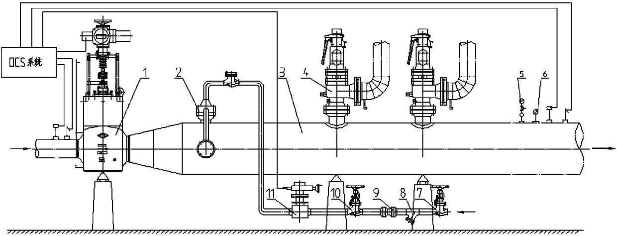
[0033] The embodiment of the present invention discloses a temperature and pressure reduction device to solve the problems of poor quality of desuperheating steam and small adjustable range of traditional temperature and pressure reduction devices.

[0034] The following will clearly and completely describe the technical solutions in the embodiments of the present invention with reference to the accompanying drawings in the embodiments of the present invention. Obviously, the described embodiments are only some, not all, embodiments of the present invention. Based on the embodiments of the present invention, all other embodiments obtained by persons of ordinary skill in the art without making creative efforts belong to the protection scope of the present invention.

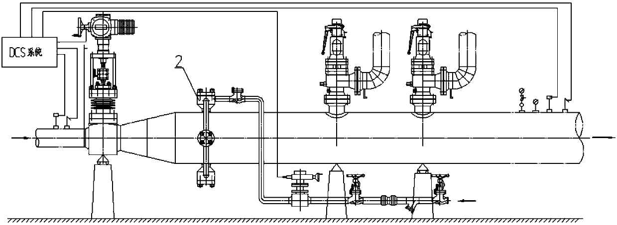
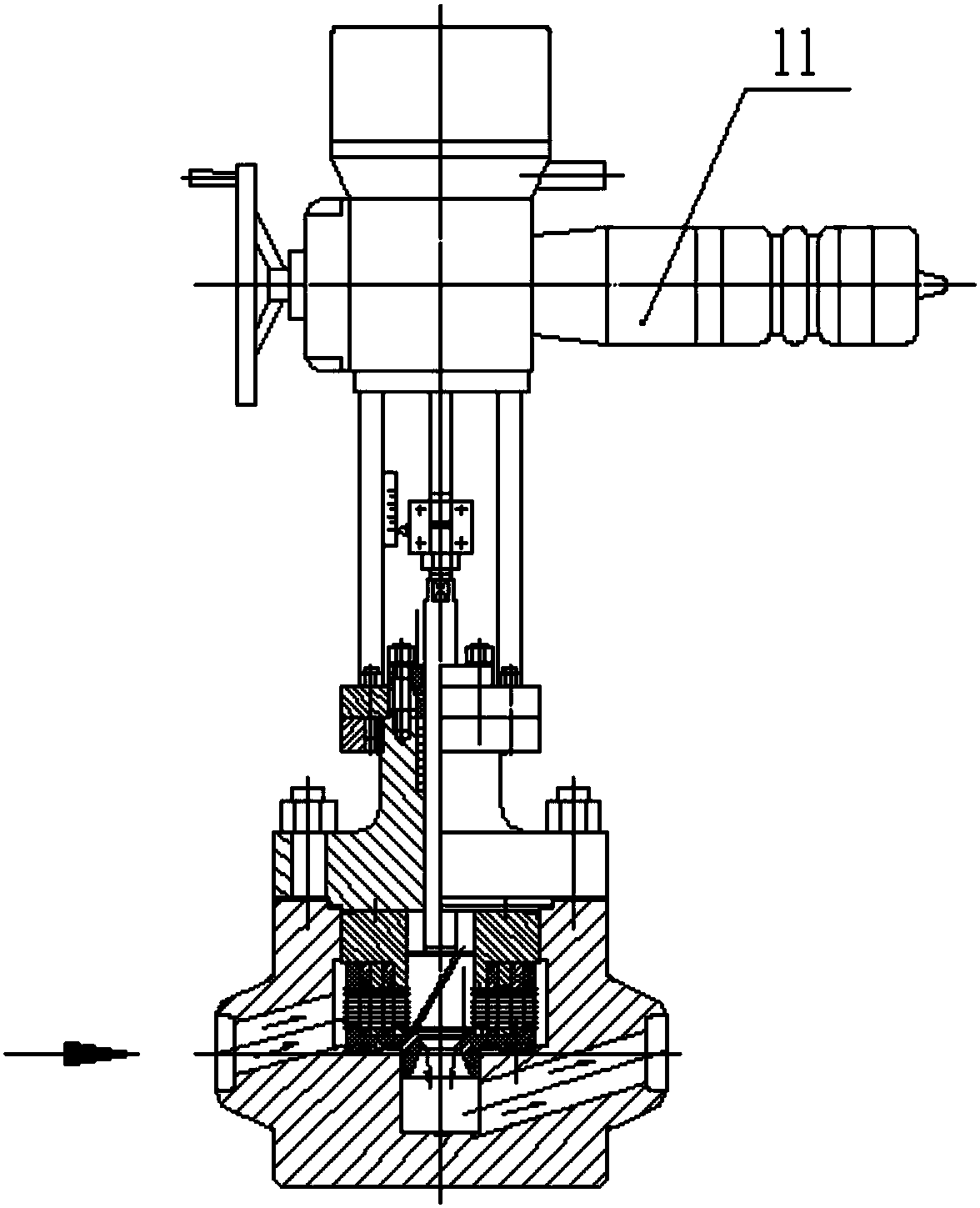
[0035] see figure 1 , 2 as shown, figure 1 A schematic structural diagram of a temperature and pressure reduction device provided by an embodiment of the present invention; figure 2 It is a structural schemati...


PUM


Abstract

The invention discloses a temperature and pressure reduction device. The temperature and pressure reduction device comprises a pressure reduction valve with one end connected with a steam inlet end, wherein the other end of the pressure reduction valve is connected with a steam mixing pipeline provided with a steam outlet end, a temperature reduction system and a safety protection system are sequentially arranged on the steam mixing pipeline, and an adjustment valve used for adjusting temperature reduction water is arranged in a temperature reduction branch where the temperature reduction system is located; and the temperature reduction system comprises a temperature reduction nozzle assembly, the temperature reduction nozzle assembly comprises a nozzle main body, a pressure accumulation cavity and a medium flow channel communicating with the pressure accumulation cavity are formed in the nozzle main body, a movable nozzle core matched with the pressure accumulation cavity is arrangedin the pressure accumulation cavity to form an airtight cavity body, the nozzle main body is elastically connected with the movable nozzle core and opened when the pressure of the pressure accumulation cavity is greater than elasticity, the movable nozzle core forms a conical surface in the pressure accumulation cavity, a preset angle is formed between the medium flow channel and the axis of the movable nozzle core, and a preset chamfer angle is formed between the medium flow channel and the conical surface, so that water flow is ejected onto the conical surface and rotationally ejected out. Due to the arrangement, the use performance and the adjustment performance of the device are improved.

Description

technical field [0001] The invention relates to the field of valves, more specifically, to a temperature and pressure reduction device. Background technique [0002] The output steam evaporated by the boiler is generally above the parameters of high temperature and high pressure. In the equipment where steam is used as the power source, specific steam pressure and temperature are often required. Temperature and decompression. Traditional desuperheating and decompression devices have problems such as small adjustable range of flow rate, poor quality of steam after desuperheating, low control precision, and large noise and vibration. [0003] To sum up, how to effectively solve the problems of poor desuperheating steam quality and small adjustable range of traditional desuperheating and decompression devices is an urgent problem for those skilled in the art. Contents of the invention [0004] In view of this, the purpose of the present invention is to provide a temperature...

Claims


Application Information

Patent Timeline
Patent Type & Authority Applications(China)
IPC IPC(8): F17D1/06F17D3/01F22G5/12
CPCF17D1/06F17D3/01F22G5/12
Inventor 张明陈立龙陈卫平倪雪琴王小强
Owner HANGZHOU WORLDWISE VALVE
Learn More