
Solenoid valve circuit failure switching and alarming circuit for diesel engine emergency shutdown and method thereof

A technology of emergency stop and alarm circuit, which is applied in the direction of mechanical equipment, engine components, machines/engines, etc., and can solve the problem that the alarm light indication cannot be seen

Inactive Publication Date: 2018-04-13
JIANGSU UNIV OF SCI & TECH
View PDF2 Cites 2 Cited by
  • Summary
  • Abstract
  • Description
  • Claims
  • Application Information

AI Technical Summary

Problems solved by technology

It seems that the above functions have been realized, but in addition to the existing problems and defects of a diesel engine emergency stop solenoid valve loop failure alarm circuit and its alarm method with the patent application number: 201510846141.X, there is also a diesel power supply for the alarm light The electricity generated by the engine is directly powered, and the warning light indicator cannot be seen after the emergency stop of the diesel generator, because when controlling the emergency stop of the diesel generator, the user cannot stare at the warning light, only after the emergency stop will pay attention to the warning light Indicates the status, but the diesel generator does not generate electricity after an emergency stop, so why is there any power output

Method used


Image

  • Solenoid valve circuit failure switching and alarming circuit for diesel engine emergency shutdown and method thereof

Examples


Embodiment Construction

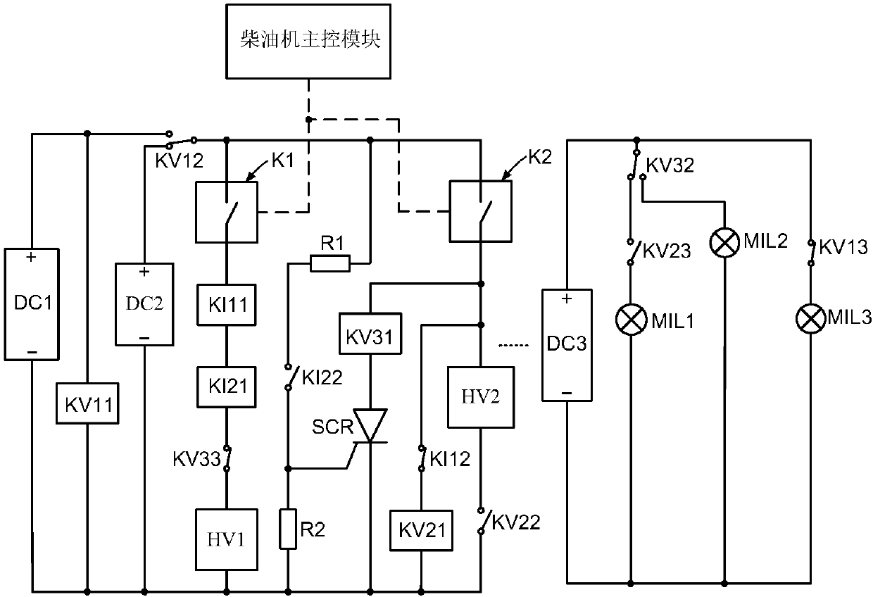
[0068] Such as figure 1As shown, the diesel engine emergency stop solenoid valve circuit failure switch, alarm circuit, including parking power DC1, backup power DC2, alarm power DC3, first voltage type relay, second voltage type relay, third voltage type relay, first current type Relay, second current type relay, emergency stop solenoid valve HV1, backup solenoid valve HV2, first fault indicator light MIL1, second fault indicator light MIL2, third fault indicator light MIL3, first switch module K1, second switch module K2, the third switch module K3, thyristor SCR, resistor R1, and resistor R2; the first voltage relay coil KV11 is directly connected to the parking power supply DC1 in parallel, and the positive pole of the parking power supply DC1 is in two-way contact with the first voltage relay The normally open end of KV12 is connected, the positive pole of the backup power supply DC2 is connected with the normally closed end of the first voltage type relay bidirectional c...


PUM


Abstract

The invention discloses a solenoid valve circuit failure switching and alarming circuit for diesel engine emergency shutdown and a method thereof. The solenoid valve circuit failure switching and alarming circuit is characterized in that the solenoid valve circuit failure switching and alarming circuit comprises an emergency shutdown solenoid valve circuit, an emergency shutdown standby solenoid valve circuit, an emergency shutdown solenoid valve overcurrent switching control circuit, an emergency shutdown solenoid valve undercurrent switching control circuit, a voltage-type relay, a shutdownpower supply failure alarming circuit, an emergency shutdown solenoid valve overcurrent alarming circuit and an emergency shutdown solenoid valve undercurrent alarming circuit, wherein the emergency shutdown solenoid valve circuit is connected with an undercurrent detection current relay and an overcurrent detection current relay in series; and the voltage-type relay detects shutdown power supplyfailure and switches a power supply to a standby power for power supplying. The method is characterized in that in case of shutdown power supply failure, the power supply is directly switched to the standby power for power supplying, and an indicator light conducts alarming and prompting; during undercurrent or overcurrent of an emergency shutdown solenoid valve, the emergency shutdown solenoid valve is switched to a standby solenoid valve for emergency shutdown, and corresponding alarming and prompting of the indicator light are conducted; and during overcurrent of the emergency shutdown solenoid valve, the emergency shutdown solenoid valve circuit is cut off, and short circuit protection is conducted on the emergency shutdown solenoid valve circuit.

Description

technical field [0001] The invention belongs to the technical field of diesel engine safety protection, and in particular relates to a diesel engine emergency stop solenoid valve circuit failure switch, an alarm circuit and an implementation method thereof. Background technique [0002] At present: the emergency stop system of diesel engine has two ways of cutting off gas and cutting off oil for emergency stopping of diesel engine. An oil cut-off electromagnetic control valve device is installed on the oil circuit, and the oil can be cut off in an emergency when a fault occurs. These solenoid-operated valves are commonly referred to as emergency stop solenoid valves. When the solenoid valve used in the emergency stop solenoid valve is a normally closed solenoid valve, the designed circuit of the emergency stop solenoid valve is a demagnetized (power-off) stop; when the solenoid valve used in the emergency stop solenoid valve is a normally open solenoid valve The designed e...

Claims


Application Information

Patent Timeline
Patent Type & Authority Applications(China)
IPC IPC(8): F02B77/08F02B63/04
CPCF02B77/08F02B63/04
Inventor 凌青华王长宝齐亮夏永锋张海洋
Owner JIANGSU UNIV OF SCI & TECH
Learn More