
Fixing protection mechanism for continuous adjustment of pressure on cylindrical lithium battery

A fixed protection and lithium battery technology, which is applied in the testing of machines/structural components, measuring devices, vibration testing, etc., can solve problems such as failure to achieve a fixed effect, damage to test samples, etc.

Pending Publication Date: 2018-04-10
HEBEI UNIV OF TECH
View PDF0 Cites 6 Cited by
  • Summary
  • Abstract
  • Description
  • Claims
  • Application Information

AI Technical Summary

Problems solved by technology

[0002] The key to the vibration experiment is to ensure that there is no relative displacement between the experimental sample and the vibration plane. This requires the test sample to be placed on a certain fixed mechanism. While ensuring that no relative displacement occurs, the applied pressure must also be controlled within a certain range. The reason The reason is that the test sample will be damaged if the pressure is too high, and the fixing effect will not be achieved if the pressure is too small
For the vibration experiment of cylindrical lithium batteries, it is even more necessary for the samples to be carried out in a certain energized environment. There are no products that can meet the above requirements for the existing fixing mechanisms on the market.

Method used


Image

  • Fixing protection mechanism for continuous adjustment of pressure on cylindrical lithium battery
  • Fixing protection mechanism for continuous adjustment of pressure on cylindrical lithium battery
  • Fixing protection mechanism for continuous adjustment of pressure on cylindrical lithium battery

Examples


Embodiment Construction

[0021] The detailed working method of this patent will be described below through specific embodiments and accompanying drawings.

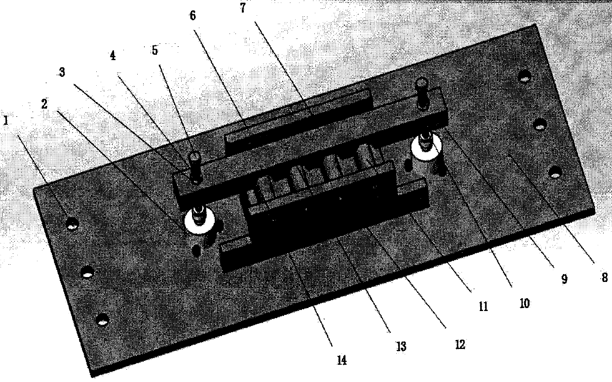
[0022] like figure 1 As shown, because the present embodiment is a symmetrical structure, so for the bottom plate fixing hole 1, stepper motor 2, nut 3, spring 4, screw rod 5, fixed electrode 7, movable nut 10, and movable electrode 12 in the figure all refer to Substitute both side components.

[0023] like figure 1 As shown, the fixed electrode electrode 7 is installed on the horizontal pressing plate 6, and the position of this electrode is fixed and cannot move back and forth in the horizontal direction.

[0024] like figure 1 As shown, the fixed electrode 7 is located at the same height as the horizontal platen 6 and the placed cylindrical lithium battery electrode.

[0025] like figure 1 As shown, the horizontal pressing plate on the other side of the horizontal pressing plate 6 is made of the same material as the horizontal pressing pl...


PUM


Abstract

The invention discloses a fixing protection mechanism for the continuous adjustment of the pressure on a cylindrical lithium battery, and the mechanism is used for fixing the lithium battery in a vibration test, enabling the lithium battery not to generate displacement relative to the work plane of a vibrating table, guaranteeing the good contact of the lithium battery with a charging and discharging electrode and avoiding the impact on the charging and discharging process of the lithium battery. The protection mechanism comprises a vertical fixing part and a horizontal fixing part. Two ends of a vertical pressure plate in a vertical fixing part are provided with springs, and a screw passes through the springs and the vertical pressure plate. The other end of the screw is provided with a moving nut which is connected with a stepping motor. When the mechanism is in use, the nut synchronously rotates with the motor, and a program controls the motor to rotate in a forwarding or reverse manner, thereby enabling a horizontal pressure plate to rise or fall. The inner side of a pressure groove of the vertical pressure plate is provided with a pressure sensor and a temperature sensor, andthe pressure sensor collects the pressure applied by the vertical pressure plate to the lithium battery in real time, and is used for carrying out the program control of the stepping motor to carry out the continuous operation, thereby guaranteeing that the pressure on the lithium battery in a battery groove is within a certain range. The temperature sensor collects the temperature data in real time in a battery charging and discharging process. The horizontal fixing part enables the lithium battery to be fixed in the horizontal direction through the two horizontal pressure plates and a power-on electrode, and a power-on current is provided by the electrode.

Description

technical field [0001] The invention designs a cylindrical lithium battery pressure continuous adjustment fixed protection mechanism technical background [0002] The key to the vibration experiment is to ensure that there is no relative displacement between the experimental sample and the vibration plane. This requires the test sample to be placed on a certain fixed mechanism. While ensuring that no relative displacement occurs, the applied pressure must also be controlled within a certain range. The reason Because the test sample will be damaged if the pressure is too high, and the fixing effect will not be achieved if the pressure is too small. For the vibration experiment of cylindrical lithium batteries, it is even more necessary for the samples to be carried out in a certain energized environment. There are no products that can meet the above requirements for the existing fixing mechanisms on the market. Contents of the invention [0003] The purpose of the present ...

Claims


Application Information

Patent Timeline
IPC IPC(8): G01M7/02
CPCG01M7/027Y02E60/10
Inventor 李文华杜乐范文奕焦志鹏
Owner HEBEI UNIV OF TECH
Learn More