
Barrier gate

A technology of barrier gates and gate levers, applied in the field of barrier gates, can solve problems such as complex procedures, autotransmission errors, and affecting the normal operation of barrier gates, and achieve the effects of avoiding secondary connections, avoiding autotransmission errors, and reducing wear

Inactive Publication Date: 2018-04-10
浙江航兴电机有限公司
View PDF3 Cites 0 Cited by
  • Summary
  • Abstract
  • Description
  • Claims
  • Application Information

AI Technical Summary

Problems solved by technology

In the prior art, the main shaft of the barrier gate connected to the gate lever and the output shaft of the reducer are connected through a linkage mechanism. This structure has complicated installation procedures and requires very high coaxiality between the two shafts. Moreover, this secondary connection structure may cause self-propagation errors when the main shaft and output shaft are connected and transmitted, which will affect the normal operation of the barrier gate.

Method used


Image

  • Barrier gate

Examples


Embodiment Construction

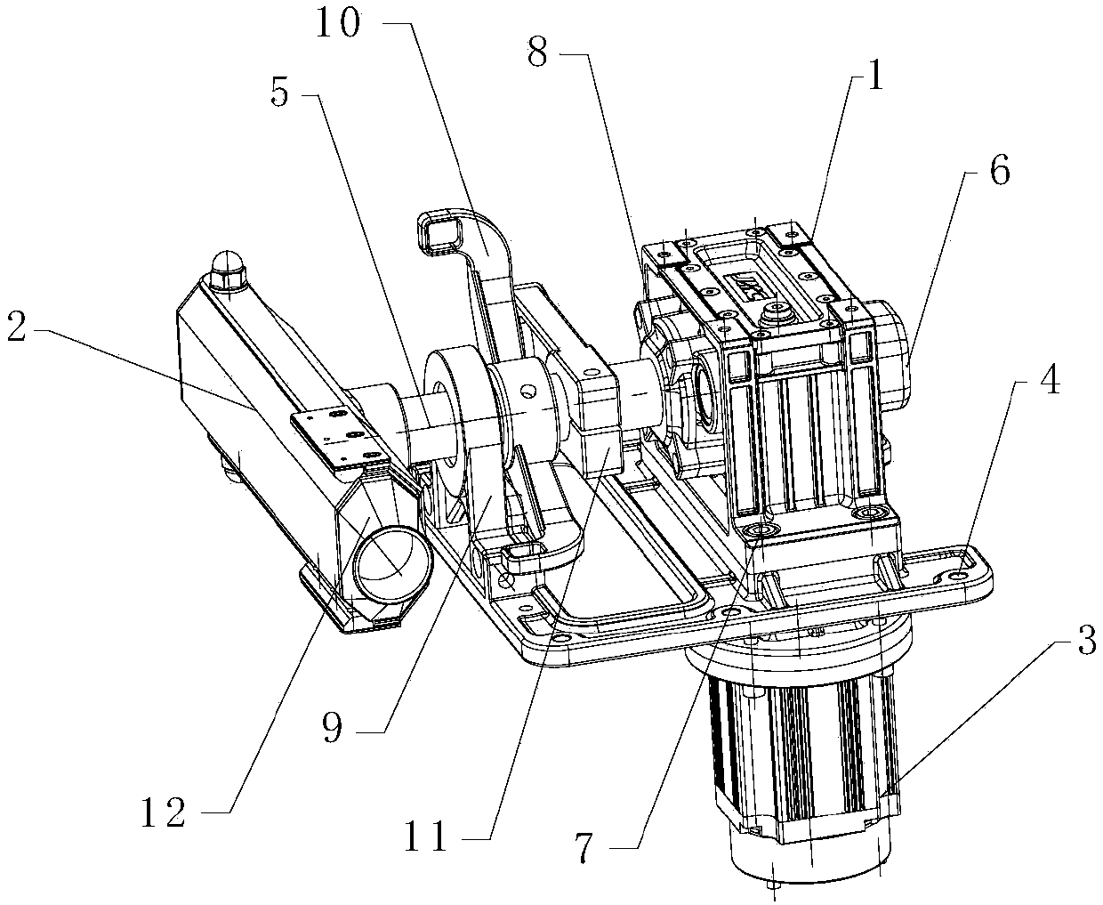
[0020] The core of the present invention is to provide a barrier gate. The output shaft of the reducer is used as the main shaft of the barrier gate, which avoids the secondary connection between the output shaft and the main shaft, thereby avoiding the self-propagation error, and at the same time reducing the impact of the output shaft on the inside of the reducer. Wear and tear of parts.

[0021] In order to make the purpose, technical solutions and advantages of the embodiments of the present invention clearer, the technical solutions in the embodiments of the present invention will be clearly and completely described below in conjunction with the drawings in the embodiments of the present invention. Obviously, the described embodiments It is a part of embodiments of the present invention, but not all embodiments. Based on the embodiments of the present invention, all other embodiments obtained by persons of ordinary skill in the art without making creative efforts belong t...


PUM


Abstract

The invention discloses a barrier gate which comprises a speed reducer, a brake bar, a motor and a mounting seat, wherein the speed reducer is arranged on the mounting seat, the input end of the speedreducer is connected with the output end of the motor, the speed reducer is provided with a cavity for mounting of the output shaft of the speed reducer; one end, located in the cavity, of the outputshaft is fixedly connected with a rear axle cover of the speed reducer; and one end, located outside the cavity, of the output shaft is fixedly connected with the brake bar by a slot. According to the invention, the output shaft of the speed reducer is arranged in the cavity of the speed reducer, and two ends of the output shaft are respectively fixedly connected with the brake bar and the rear axle cover of the speed reducer, that is, the output shaft of the speed reducer is used as a main shaft of the barrier gate, and therefore, secondary connection of the output shaft and the main shaft is avoided, and further self-rotation error is avoided, and abrasion of the output shaft to internal parts of the speed reducer is reduced.

Description

technical field [0001] The invention relates to the field of road equipment, in particular to a barrier gate. Background technique [0002] Barrier gate is a channel entrance and exit management equipment specially used to restrict motor vehicles on the road. It is generally composed of reducer, motor, transmission mechanism, bearing seat, chassis, brake lever and other parts. In the prior art, the main shaft of the barrier gate connected to the gate lever and the output shaft of the reducer are connected through a linkage mechanism. This structure has complicated installation procedures and requires very high coaxiality between the two shafts. Moreover, this secondary connection structure may cause an autopropagation error when the main shaft and the output shaft are connected and transmitted, affecting the normal operation of the barrier gate. [0003] Therefore, how to provide a solution to the above technical problems is a problem that those skilled in the art need to s...

Claims


Application Information

Patent Timeline
Patent Type & Authority Applications(China)
IPC IPC(8): E01F13/06
CPCE01F13/06
Inventor 刘少宏范国和江亚华艾叶平
Owner 浙江航兴电机有限公司
Learn More