
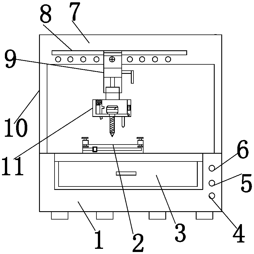
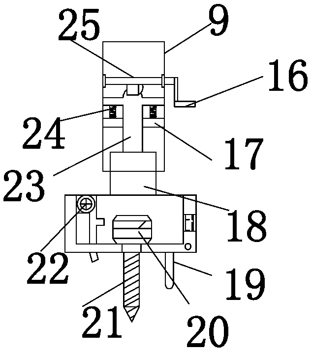
Perforating device for silicon carbide rod machining

A punching device and carbon-silicon rod technology, which is applied to fine working devices, stone processing equipment, manufacturing tools, etc., can solve the problems of users' hands getting dirty and unable to adapt to intermittent punching in different areas.

Inactive Publication Date: 2018-04-10
河南格锐新材料科技有限公司
View PDF0 Cites 1 Cited by
  • Summary
  • Abstract
  • Description
  • Claims
  • Application Information

AI Technical Summary

Problems solved by technology

[0003] The purpose of the present invention is to solve the problem that the existing punching device in the prior art cannot adapt to the intermittent punching of different regions when punching holes, and after punching, it is necessary for the user to place the silicon carbon rod Picking up, causing the user's hands to get dirty, etc., and a punching device for carbon silicon rod processing is proposed

Method used


Image

  • Perforating device for silicon carbide rod machining
  • Perforating device for silicon carbide rod machining
  • Perforating device for silicon carbide rod machining

Examples


Embodiment Construction

[0015] The following will clearly and completely describe the technical solutions in the embodiments of the present invention with reference to the accompanying drawings in the embodiments of the present invention. Obviously, the described embodiments are only some, not all, embodiments of the present invention.

[0016] In describing the present invention, it should be understood that the terms "upper", "lower", "front", "rear", "left", "right", "top", "bottom", "inner", " The orientation or positional relationship indicated by "outside", etc. is based on the orientation or positional relationship shown in the drawings, and is only for the convenience of describing the present invention and simplifying the description, rather than indicating or implying that the referred device or element must have a specific orientation, so as to Specific orientation configurations and operations, therefore, are not to be construed as limitations on the invention.

[0017] refer to Figure ...


PUM


Abstract

The invention discloses a punching device for processing silicon carbon rods, which comprises a base, a fixed cylinder and a motor box. A blower switch is arranged on the right side of the base, a motor switch is arranged above the blower switch, and a motor switch is arranged above the motor switch. There is a light switch, the upper part of the base is fixedly connected to the frame, the top of the frame is fixedly connected to the top box, a rotating rod runs through the top of the fixed cylinder, and an extrusion block is arranged in the middle of the rotating rod, and the right end of the rotating rod A handle is provided, and a motor is installed inside the motor box. In the present invention, a partition is arranged inside the fixed cylinder, and return springs are installed at the left and right ends of the top of the partition. The pressing block squeezes the lifting rod and resets it to avoid drilling too deep, which may cause drilling failure.

Description

technical field [0001] The invention relates to a punching device, in particular to a punching device for processing silicon carbon rods. Background technique [0002] At present, carbon silicon rods are colorless cubic or hexagonal crystals, and the surface is blue-black when oxidized or contains impurities. Silicon carbon rods have a three-dimensional spatial structure composed of silicon atoms and carbon atoms, and each atom is surrounded by other four atoms. There are many variants of silicon carbon rods, most of which are diamond, sphalerite and fiber mineral lattices. According to the needs of the market, silicon carbon rods need to be drilled. The existing punching device cannot It is suitable for intermittent drilling in different areas, and after drilling, the user needs to pick up the silicon carbon rod by hand, which will cause the user's hands to get dirty. Contents of the invention [0003] The purpose of the present invention is to solve the problem that th...

Claims


Application Information

Patent Timeline
IPC IPC(8): B28D5/02B28D5/00
CPCB28D5/021B28D5/0076B28D5/0082
Inventor 胡耀伟
Owner 河南格锐新材料科技有限公司
Learn More