High-voltage high-power supply discharging device

A high-power power supply and discharge device technology, which is applied to output power conversion devices, electrical components, etc., can solve problems such as hidden safety hazards, shutdown, and long natural discharge time of bus capacitors, and achieve the effect of avoiding danger.

Inactive Publication Date: 2018-04-06
HUBEI SANJIANG AEROSPACE WANFENG TECH DEV
View PDF5 Cites 4 Cited by
  • Summary
  • Abstract
  • Description
  • Claims
  • Application Information

AI Technical Summary

Problems solved by technology

The natural discharge time of the bus capacitor is long, which brings inconvenience to maintenance and poses a safety hazard
[0003] Commonly used bus capacitor discharge methods: one is to manually control the connection and shutdown of the discharge circuit through an external discharge circuit. This method requires external power supply to the discharge circuit and requires manual operation, which is not flexible enough and has potential safety hazards; the other A switch circuit to control the connection and shutdown of the discharge circuit
Utility model patent CN2012207503 "a driver and its bus capacitor discharge circuit" and utility model patent CN2013208386 "a bus capacitor discharge device" both use switching circuits to control the connection and shutdown of the discharge circuit, "a driver and Its bus capacitor discharge circuit" has the following problems: when the bus capacitor discharges to a certain extent, the discharge circuit will be closed, and the bus capacitor power has not been fully discharged, and there are still potential safety hazards; "a bus capacitor discharge device" controls the discharge circuit. The control power supply for input and disconnection is composed of an AC power supply and a rectifier circuit. The high-power power supply for high-voltage DC input and DC output needs to be connected to the control power supply externally, which is not convenient and increases costs.

Method used


Image

  • High-voltage high-power supply discharging device

Examples


Embodiment Construction

[0019] In order to make the object, technical solution and advantages of the present invention clearer, the present invention will be further described in detail below in conjunction with the accompanying drawings and embodiments. It should be understood that the specific embodiments described here are only used to explain the present invention, not to limit the present invention. In addition, the technical features involved in the various embodiments of the present invention described below may be combined with each other as long as they do not constitute a conflict with each other.

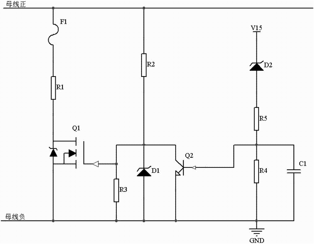
[0020] A high-voltage and high-power power supply discharge device provided by the present invention includes an auxiliary power supply, a control switch, a switch circuit, a discharge resistor and a fuse.

[0021] The control switch is used to control the on and off of the switch circuit, including Zener diode D2, transistor Q2, capacitor C1 and voltage divider resistors R4, R5, the negative po...


PUM


Abstract

The invention belongs to the technical field of power supplies and discloses a high-voltage high-power supply discharging device comprising an auxiliary power supply, a control switch, a switch circuit and a bleeder resistor, wherein one end of the control switch is connected to the auxiliary power supply; the other end of the control switch is connected to the switch circuit; the on/off state ofthe switch circuit is controlled by the voltage change of the auxiliary power supply; one end of the bleeder resistor is connected to the positive terminal of a bus; the other end of the bleeder resistor is connected to the negative pole of the bus through the switch circuit; the bleeder resistor is connected in parallel with the bus when the switch circuit is switched on; high voltage on the busof the power supply is released by the bleeder resistor; and the bleeder resistor is disconnected from the bus when the switch circuit is switched off. The high-voltage high-power supply discharging device can quickly and safely discharge the high voltage on the bus when a high-voltage high-power supply is powered off, and automatically cuts off a discharge circuit when the high-voltage high-powersupply recovers power supply, without affecting the normal operation of the high-voltage high-power supply.

Description

technical field [0001] The invention belongs to the technical field of power electronics, and more specifically relates to a high-voltage and high-power power supply discharge device. Background technique [0002] In the vehicle power supply system, the high-voltage and high-power power supply converts the high-voltage input voltage into a safe and stable DC low output voltage. A large number of large-capacity capacitors are often connected in parallel on the bus for filtering. The bus capacitor can provide instantaneous high current. When the system is powered on, the bus capacitor is always in a charging state. When the system is powered off, the large-capacity bus capacitor instantly releases a large amount of power. During troubleshooting of high-voltage and high-power power supplies, especially for failures caused by high-voltage and high-power power supplies not vibrating or open circuit of high-voltage and high-power power supply switches, in most cases, the voltage a...

Claims


Application Information

Patent Timeline
Patent Type & Authority Applications(China)
IPC IPC(8): H02M1/32
CPCH02M1/32H02M1/322
Inventor 王莉马高育常超乔洪涛陈圣荣汪庆
Owner HUBEI SANJIANG AEROSPACE WANFENG TECH DEV
Why Eureka
Try Eureka