
Key

A key and key cap technology, applied in electrical components, electrical switches, circuits, etc., can solve the problems of insensitive button pressing and triggering, and the key cap and key cap are easy to fall off, so as to improve the trigger sensitivity and pressing feel, solve the problem of easy falling off, The effect of increasing the pulling force

Active Publication Date: 2018-04-06
DARFON ELECTRONICS (SUZHOU) CO LTD +1
View PDF7 Cites 1 Cited by
  • Summary
  • Abstract
  • Description
  • Claims
  • Application Information

AI Technical Summary

Problems solved by technology

[0004] The purpose of the present invention is to provide a key that uses an auxiliary bracket to trigger the trigger switch on the film circuit board, so as to solve the problems that the key cap is not sensitive enough to be pressed and the key cap is easy to fall off due to the decrease of the pulling force of the key cap.

Method used


Image

  • Key
  • Key
  • Key

Examples


Embodiment Construction

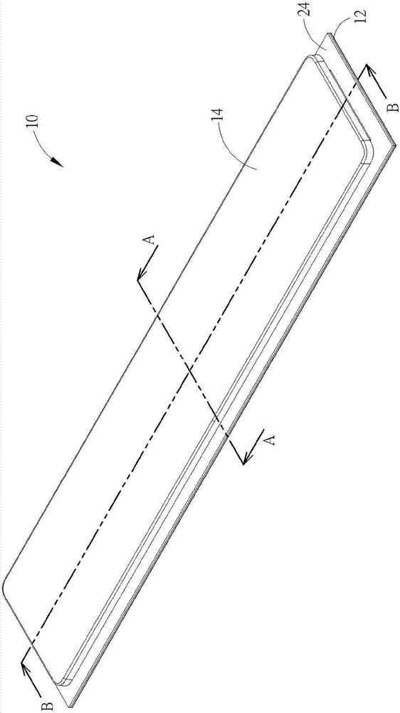
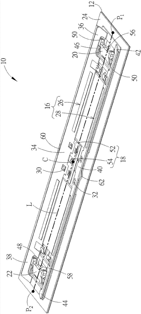
[0026] see figure 1 as well as figure 2 , figure 1 It is a three-dimensional schematic diagram of the button 10 proposed according to an embodiment of the present invention, figure 2 for figure 1 The three-dimensional schematic view of the button 10 omitting the keycap 14. like figure 1 as well as figure 2 As shown, the button 10 can preferably be a long button (also known as a multiple button) and includes a bottom plate 12, a keycap 14, a lifting mechanism 16, a rebound device 18, a first auxiliary bracket 20, a second auxiliary bracket 22 and a thin film circuit plate 24. The keycap 14 has a keycap major axis L. As shown in FIG. The lifting mechanism 16 is arranged between the bottom plate 12 and the keycap 14. The keycap 14 moves up and down between the pressed position and the unpressed position relative to the bottom plate 12 via the lifting mechanism 16. The lifting mechanism 16 includes a first plate-like bracket 26 and a second Plate support 28. The first ...


PUM


Abstract

A key comprises a base plate, a key cap having a key cap long shaft, a lifting mechanism, a rebounding device, a first auxiliary support and a thin film circuit board. The lifting mechanism is arranged between the base plate and the key cap to move the key cap up and down, the lifting mechanism comprises a first plate-shaped support and a second plate-shaped support which are opposite to each other, can be pivotably connected with the base plate and are abutted against the key cap, and a first end-piece portion of the first plate-shaped support and a second end-piece portion of the second plate-shaped support are adjacent to an end point of the key cap long shaft. The rebounding device is located between the first plate-shaped support and the second plate-shaped support to drive the key cap to return. The first auxiliary support is pivoted to the key cap and the base plate, and is arranged between the first end-piece portion and the second end-piece portion to form a first triggering salient point. The thin film circuit board is arranged on the base plate and is provided with a first triggering switch. When the key cap is pressed, the first triggering salient point triggers the first triggering switch. The key can greatly improve the triggering flexibility of the key and the pressing hand feeling.

Description

technical field [0001] The invention relates to a button, in particular to a button using an auxiliary bracket to trigger a trigger switch on a film circuit board. Background technique [0002] As far as current personal computer usage habits are concerned, the keyboard is one of the indispensable input devices for inputting characters, symbols or numbers. Not only that, but all consumer electronic products in daily life or large-scale processing equipment used in the industry need to be equipped with a key structure as an input device to operate the above-mentioned electronic products and processing equipment. [0003] The distance of the up and down movement of the traditional key is long, so it is easy to install an elastic body (such as a bowl-shaped rubber body) under the key cap, so that when the key cap is pressed down, the elastic body is also compressed downward to generate elastic force , and when the keycap is released, the elastic force generated by the elastic ...

Claims


Application Information

Patent Timeline
Patent Type & Authority Applications(China)
IPC IPC(8): H01H3/12H01H13/22H01H13/85
Inventor 侯柏均杨淞富
Owner DARFON ELECTRONICS (SUZHOU) CO LTD
Learn More