
Detachable lever assembly for drain valve

A drain valve and out-of-control technology, applied in the field of start-up travel switches, can solve problems such as poor user experience, and achieve the effects of reducing frustration, improving pressing feel, and feeling good.

Active Publication Date: 2017-01-11
XIAMEN R&T PLUMBING TECH
View PDF5 Cites 0 Cited by
  • Summary
  • Abstract
  • Description
  • Claims
  • Application Information

AI Technical Summary

Problems solved by technology

However, the starting component structure disclosed in this patent only realizes the transmission of the actuating arm and the driven arm through the fastening of the block and the slot, so that when the control is out of control, pressing the button requires a large force and there is a frustrating feel. bad user experience

Method used


Image

  • Detachable lever assembly for drain valve
  • Detachable lever assembly for drain valve
  • Detachable lever assembly for drain valve

Examples


Embodiment 1

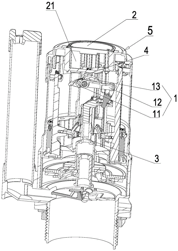
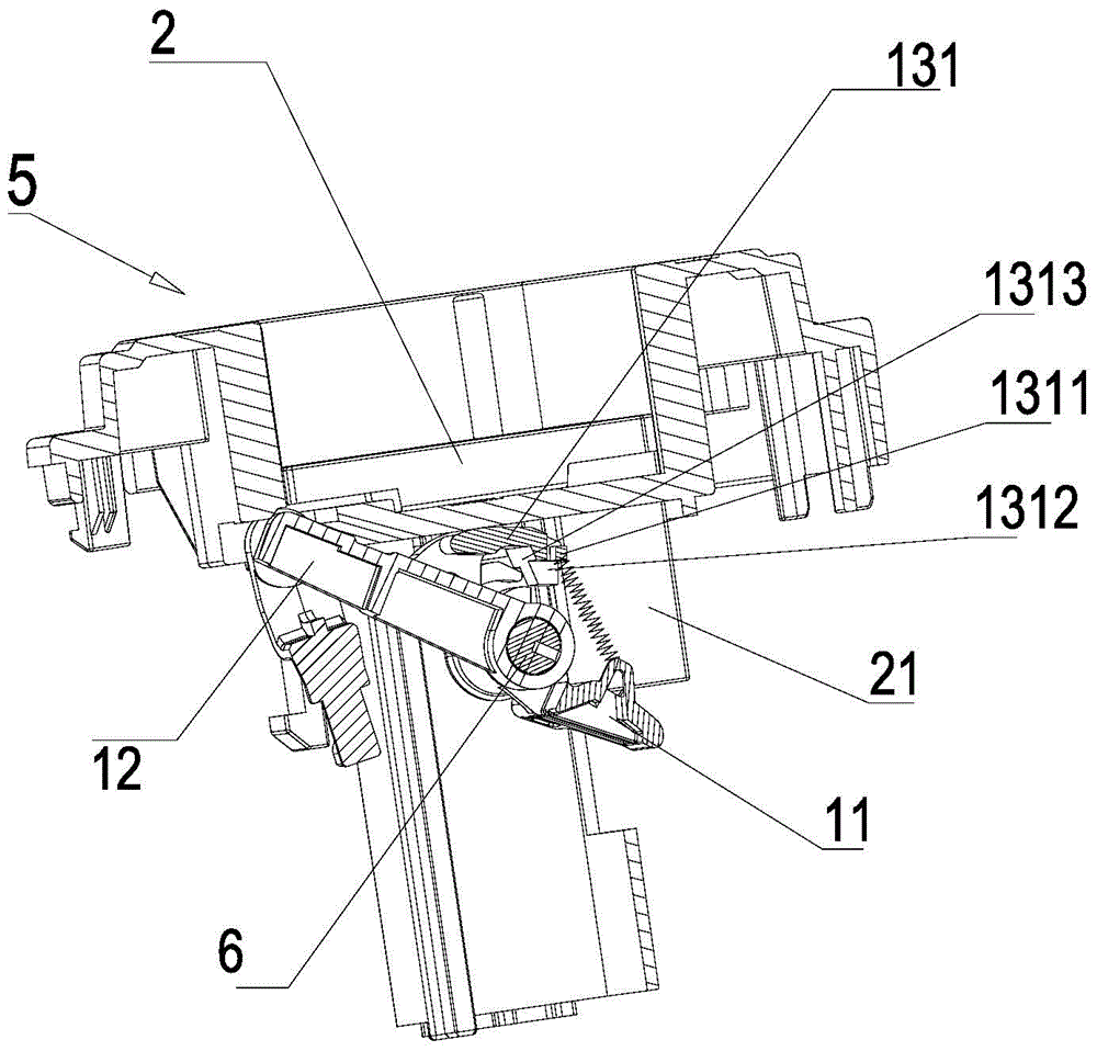
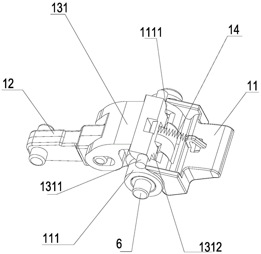
[0029] refer to Figure 1-5 , a detachable lifting rod assembly 1 for a drain valve, comprising: an actuating arm 11, a driven arm 12 and a connecting assembly 13; the actuating arm 11 is in transmission connection with the button 2 of the drain valve, and the driven arm 11 is in transmission connection with the drain assembly 3 that controls the sealing or opening of the drain valve; the upper part of the drain valve is provided with a button seat 5, the button 2 is movably mounted in the button seat 5, and the actuating arm 11 and the driven arm 12 pass through a total of The shaft part 111 is swivel and fit, and the coaxial part 111 is rotatably mounted on the key base 5 through a pin shaft 6, and the pin shaft 6 is matched with the pin hole 51 provided on the key base 5; the connecting assembly 13 includes a The coupling block 131 is swingably connected to the driven arm; one end of the coupling block 131 has a resisted block 1311 and a clamping block 1312 . The coaxial p...

Embodiment 2

[0039] refer to Figure 7 The difference between this embodiment and Embodiment 1 is that: the coupling block 131 is oscillatingly attached to the actuating arm 11 . The principle and process of realizing the function are the same as those in Embodiment 1, except that the installation position of the coupling block 131 is different, which is a simple replacement and will not be repeated here.

Embodiment 3

[0041] refer to Figure 8 The difference between this embodiment and Embodiment 1 is that: the coupling block 131 is oscillatingly attached to the valve body of the drain valve. The principle and process of realizing the function are the same as those in Embodiment 1, except that the installation position of the coupling block 131 is different, which is a simple replacement and will not be repeated here.


PUM


Abstract

The invention provides a free-control lifting rod assembly of a drain valve. The free-control lifting rod assembly comprises an actuating arm, a driven arm and a connecting assembly. The actuating arm is connected with a button of the drain valve in a transmission mode, and the driven arm is connected with a drainage assembly controlling the drain valve to be sealed or opened in a transmission mode. A limiting part is arranged inside a drain valve body. When located at a first position, the connecting assembly is limited by the limiting part, and the actuating arm and the driven arm are connected through the connecting assembly in a transmission mode. The button is pressed to make the actuating arm drive the connecting assembly to move by a preset travel distance to a second position, the connecting assembly is free of the limit of the limiting part, and therefore transmission connection between the actuating arm and the driven arm is removed. The limit on the connecting assembly is removed through the limiting part to achieve the free-control effect between the actuating arm and the driven arm; due to the free-control mode, the jerking hand feeling generated when the button is pressed can be greatly relieved, force needed for pressing the button by a user is small, and the hand feeling is good.

Description

technical field [0001] The invention relates to a start-up stroke switch of a drain valve of a bathroom water tank, in particular to an out-of-control lifting rod assembly of the drain valve. Background technique [0002] The existing drainage valve activation mechanism adopts the method of lifting the valve core to drain water by lifting the rod. The drain valve button is pressed down to activate the lifting rod to swing and lift the valve core to open the drain valve to drain water. The rising valve core is affected by the buoyancy of the float in the drain valve. Temporary positioning, after the water level of the water tank drops to a certain level, the float loses buoyancy and separates from the spool, and the spool falls to close the drain valve; but if the button is pressed continuously or the button cannot be reset normally due to jamming, the spool cannot fall, and thus cannot Close the drain valve so that the drain valve is always in the draining state, wasting wat...

Claims


Application Information

Patent Timeline
Patent Type & Authority Patents(China)
IPC IPC(8): E03D1/34
Inventor 周洪文王志忠
Owner XIAMEN R&T PLUMBING TECH
Learn More