
Method for establishing equivalent dynamic model of laminated plate based on vibration mode

A technology of dynamic model and vibration mode, which is applied in the field of system parameter identification, can solve problems such as equivalence and calculation that do not involve dynamic characteristics, and achieve the effect of ensuring accurate speed and sensitivity values ​​and small errors

Inactive Publication Date: 2018-04-06
CRRC QINGDAO SIFANG CO LTD
View PDF5 Cites 19 Cited by
  • Summary
  • Abstract
  • Description
  • Claims
  • Application Information

AI Technical Summary

Problems solved by technology

In this method, according to the mechanical characteristics of composite laminates, considering the uncertainty effect of material fiber strength in the case of limited samples, based on the non-probabilistic reliability theory, a non-probabilistic reliability evaluation model for composite laminates is established; then gradient optimization is used method, with lightweight as the goal, reliability as the constraint, and ply thickness as the optimization variable, a composite layup scheme that meets certain reliability requirements is obtained through iteration. Although a non-probabilistic reliable design method, but does not involve the equivalent and calculation of dynamic characteristics

Method used


Image

  • Method for establishing equivalent dynamic model of laminated plate based on vibration mode
  • Method for establishing equivalent dynamic model of laminated plate based on vibration mode
  • Method for establishing equivalent dynamic model of laminated plate based on vibration mode

Examples


Embodiment Construction

[0040] In order to make the purpose, technical solutions and advantages of the embodiments of the present invention more clear, the technical solutions in the embodiments will be clearly and completely described below in conjunction with the drawings in the embodiments of the present invention. The following embodiments are used to illustrate the present invention , but not to limit the scope of the present invention.

[0041] In the description of the present invention, it should be noted that the terms "upper", "lower", "front", "rear", "left", "right", "vertical", "inner", "outer" etc. The indicated orientation or positional relationship is based on the orientation or positional relationship shown in the drawings, and is only for the convenience of describing the present invention and simplifying the description, rather than indicating or implying that the referred device or element must have a specific orientation, or in a specific orientation. construction and operation, ...


PUM


Abstract

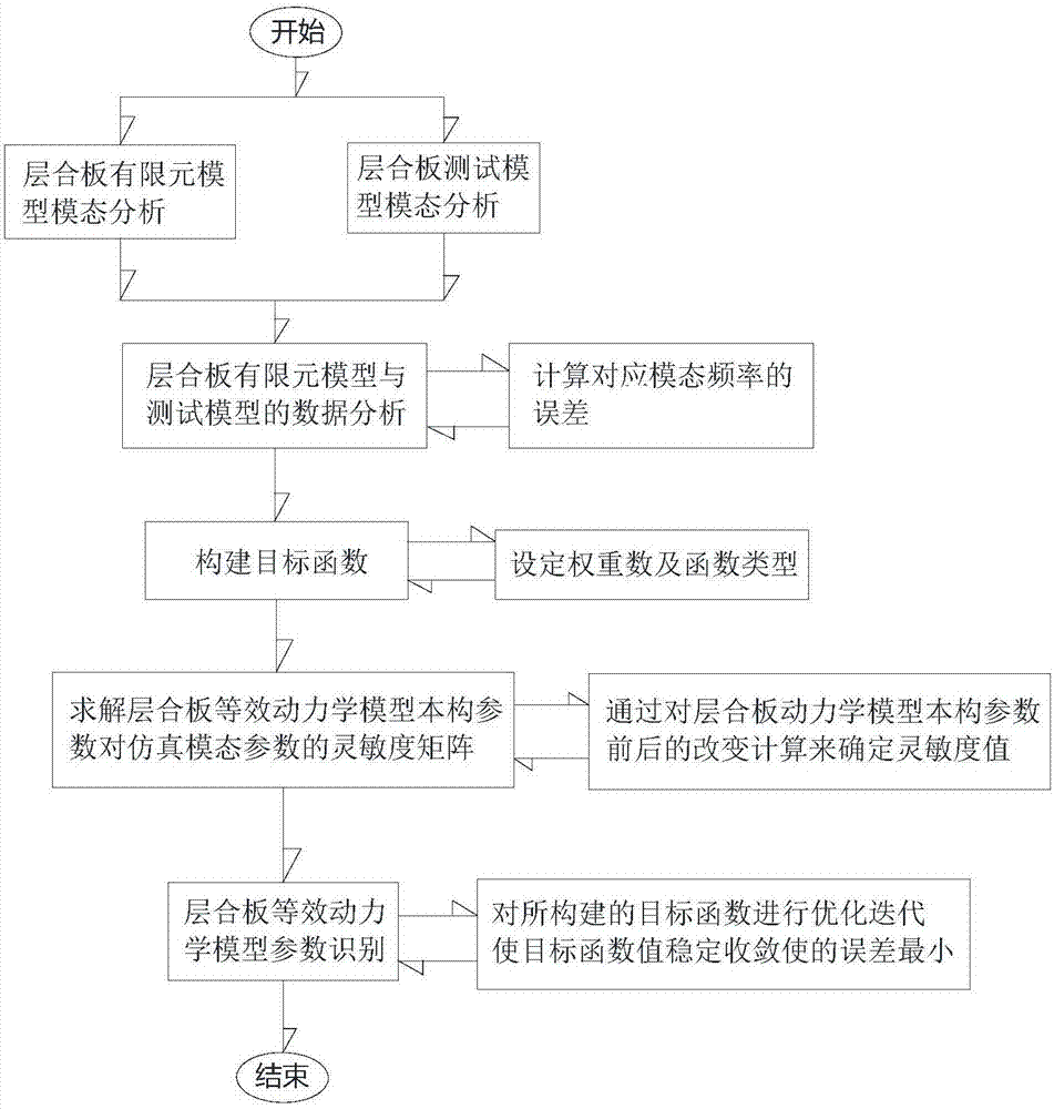
The invention discloses a method for establishing an equivalent dynamic model of a laminated plate based on a vibration mode. The method includes the step S1 of performing laminated plate finite element model modal analysis; the step S2 of performing laminated plate test model modal analysis; the step S3 of performing data analysis on a laminated plate finite element model and a test model; the step S4 of building an objective function; the step S5 of solving a sensitivity matrix of a laminated plate equivalent dynamic model constitutive parameter for a simulation modal parameter; the step S6of identifying a laminated plate equivalent dynamic model parameter. According to the method, the constitutive parameter of the laminated plate equivalent dynamic model is subjected to equivalence byadoption of an actually-measured vibration mode parameter of the laminated plate, and forceful technical support is provided for equivalent results. As test data is derived from a test of a real physical structure, the equivalent parameter is persuasive and can accurately describe the dynamic characteristics of the laminated plate in a certain frequency domain range. The method is not limited to the laminated plate only and is also suitable for other equivalent dynamic modeling of plates such as hollow plates.

Description

technical field [0001] The invention belongs to the field of system parameter identification, and in particular relates to a method for establishing an equivalent dynamic model of a laminated plate based on a vibration mode. Background technique [0002] In recent years, with the rapid development of computer simulation technology, modeling and simulation of engineering structures based on computer simulation technology has gradually become a new direction for structural design or technical improvement. The advantage of finite element modeling and simulation analysis is that the characteristics of the structure can be understood in the structural update design stage, and at the same time it can provide reasonable guidance for related tests; Modeling and simulation analysis have been widely used in many engineering fields. [0003] In the field of rail transit, composite material laminates are often used on EMUs to reduce equipment weight and improve performance; academic re...

Claims


Application Information

Patent Timeline
IPC IPC(8): G06F17/50
CPCG06F30/17G06F30/23
Inventor 王秀刚林鹏战申邹建才曲文强黄超林俊曹晓宁
Owner CRRC QINGDAO SIFANG CO LTD
Learn More