
Compression fault zone structure well logging recognition method

An identification method and fault zone technology, which is applied in earthwork drilling, wellbore/well components, buildings, etc., can solve the problems of not considering the range of curve changes, less parameter selection, and failure to identify the internal structure of the fault zone, etc.

Active Publication Date: 2016-11-09
CHINA UNIV OF PETROLEUM (EAST CHINA) +1
View PDF5 Cites 7 Cited by
  • Summary
  • Abstract
  • Description
  • Claims
  • Application Information

AI Technical Summary

Problems solved by technology

However, this method cannot effectively identify the internal structure of the fault zone during the application process due to the lack of parameter selection and the failure to consider the range of curve changes.

Method used


Image

  • Compression fault zone structure well logging recognition method
  • Compression fault zone structure well logging recognition method
  • Compression fault zone structure well logging recognition method

Examples


Embodiment Construction

[0045] Specific embodiments of the present invention will be described in detail below in conjunction with the accompanying drawings.

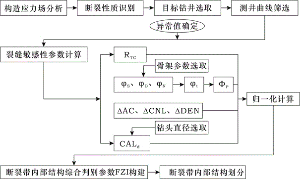
[0046] Such as figure 1 As shown in , analyze the tectonic stress field to determine whether the stress environment in the work area is a compressive stress environment, and if it is a compressive stress environment, proceed to the following steps.

[0047] The target drilling is selected, the logging curve is screened, and the abnormal values ​​a and b of the curve are determined.

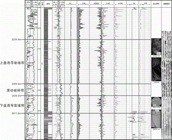
[0048] Selection and calculation of fracture sensitivity parameters: ① deep and shallow resistivity difference ratio R TC , ② three-porosity logging, ③ curve change rate, ④ borehole diameter increase rate CAL d

[0049] ① The ratio of resistivity difference between depth and shallowness R TC :

[0050] Among them, R D is the deep laterolog value or deep resistivity log value, R S is the shallow laterolog value or shallow resistivity log value; the curve F...


PUM


Abstract

The invention relates to a compression fault zone structure well logging recognition method. The compression stress environment is analyzed, target well drilling and logging curves are selected, crack sensitivity parameters are worked out, all the parameters are subjected to normalization computing, and a synthetic discriminant parameter FZI of a fault zone internal structure is established. According to the method, the fault zone internal structure can be effectively recognized through well logging data, and the selected curve type is conventional standard well logging, so that the method has quite high operability.

Description

technical field [0001] The invention belongs to the technical field of petroleum and natural gas exploration and development, and in particular relates to a logging identification method for a compressive fault zone structure. Background technique [0002] Faults are well developed in oil and gas areas, and faults control the migration and accumulation of oil and gas. Fracture is a tectonic deformation phenomenon in which rock formations rupture under the action of stress and produce obvious relative movement along the fracture surface. The rock formations on both sides of the fracture surface are squeezed and ground during the dislocation process, and the rocks are strongly broken, and at the same time, a large number of fractures associated with faults are generated on both sides (Song Daofu et al., 2010). Zhang Qinglian et al. (2010) found through field measurements that the density of structural fractures controlled by faults has an exponentially decreasing relationship...

Claims


Application Information

Patent Timeline
IPC IPC(8): E21B49/00E21B47/002
CPCE21B49/00E21B47/002
Inventor 吴孔友刘寅吴晓菲刘波裴仰文
Owner CHINA UNIV OF PETROLEUM (EAST CHINA)
Learn More