
Jacket foundation structure and construction method

A technology of foundation structure and construction method, which is applied in the field of jacket foundation, can solve the problems of troublesome grouting at the junction of piles and support rods, difficulty in controlling piling depth, high annual utilization hours, etc., and achieves convenient plugging, simple structure, The effect of preventing falling off the platform

Inactive Publication Date: 2018-04-06
虞温乐
View PDF0 Cites 4 Cited by
  • Summary
  • Abstract
  • Description
  • Claims
  • Application Information

AI Technical Summary

Problems solved by technology

Offshore wind power has less negative impact on the environment due to its rich resources, stable wind speed; the wind turbines of offshore wind power are far from the coast, with little noise and visual interference; and offshore wind turbines not only have large single-unit capacity, but also have high annual utilization hours. and does not occupy land resources. Therefore, it has developed rapidly in recent years. The fixed offshore wind turbine needs to have a specially designed foundation structure. At present, there are two types of foundation structures for offshore wind turbines, namely fixed foundation and floating foundation. Among them, the fixed foundation includes pile foundation structure, gravity foundation structure, negative pressure bucket foundation structure and jacket foundation structure; in overseas offshore wind power, the application of jacket foundation has become more and more common, and the wind turbine foundation structure mainly adopts single pile For the foundation, three-pile foundation and five-pile foundation, the piles are generally driven into the seabed by a pile driver, and it is not easy to control the depth of the piling. It is also very troublesome to grout the connection between the pile and the support rod

Method used


Image

  • Jacket foundation structure and construction method
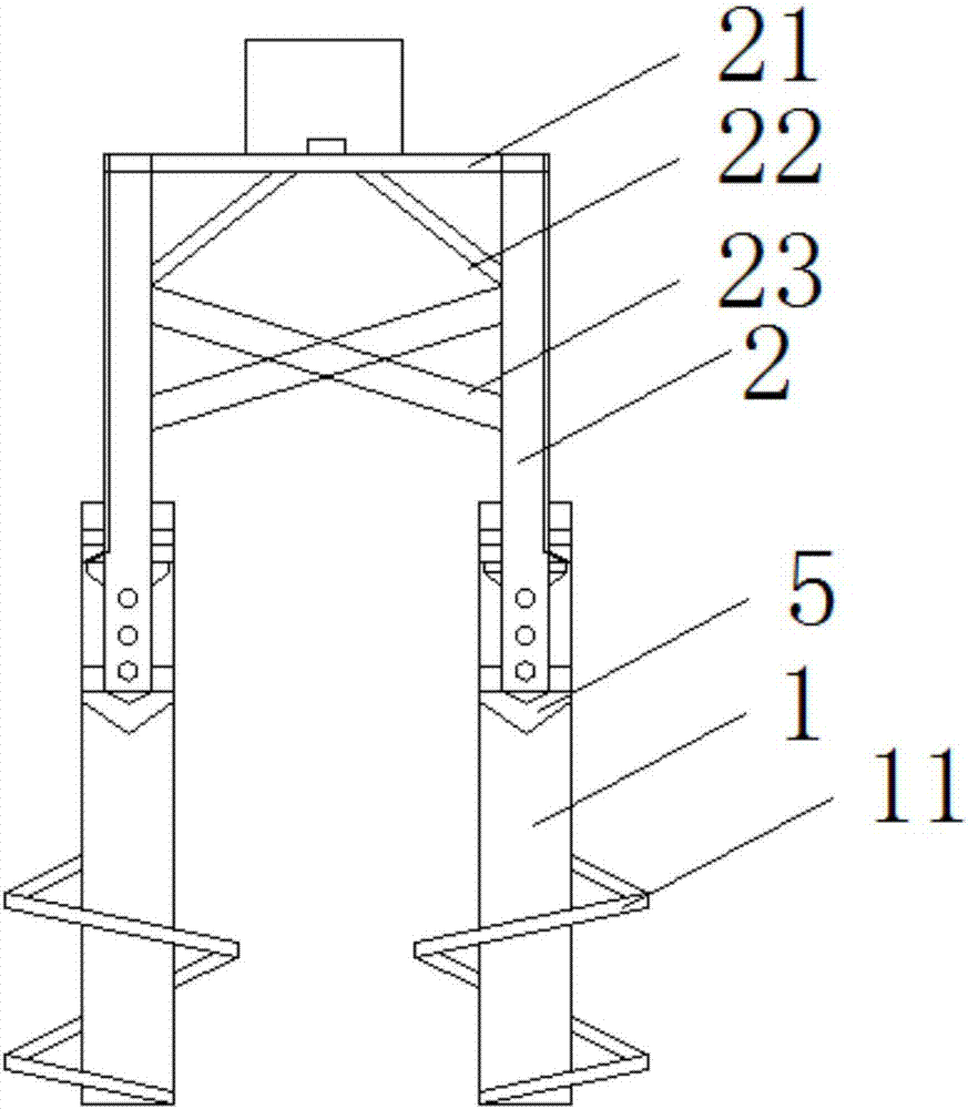
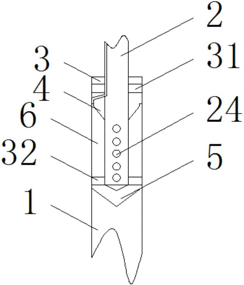
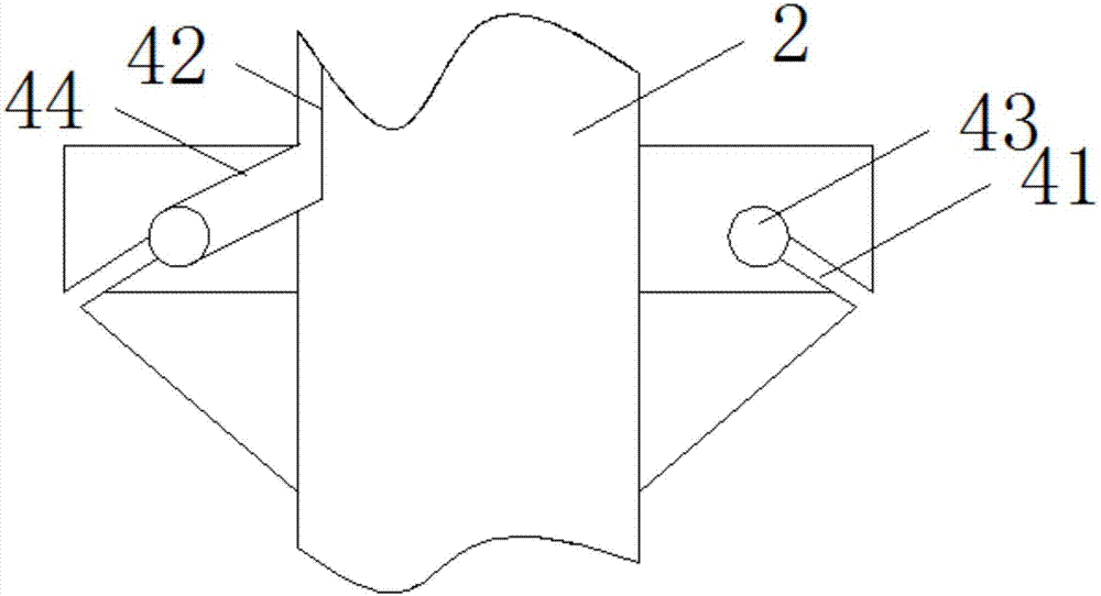
  • Jacket foundation structure and construction method
  • Jacket foundation structure and construction method

Examples


Embodiment Construction

[0021] The following will clearly and completely describe the technical solutions in the embodiments of the present invention with reference to the accompanying drawings in the embodiments of the present invention. Obviously, the described embodiments are only some, not all, embodiments of the present invention. Based on the embodiments of the present invention, all other embodiments obtained by persons of ordinary skill in the art without making creative efforts belong to the protection scope of the present invention.

[0022] see Figure 1-4 , the present invention provides a technical solution: a jacket foundation structure, including piles 1, the piles 1 have three groups of the same size and structure, the piles 1 are provided with a spiral plate 11, the piles 1 The top of the pile 1 is provided with a supporting rod 2, and a grouting chamber 6 is formed between the pile 1 and the supporting rod 2. The top of the supporting rod 2 is provided with a platform 21, and the bo...


PUM


Abstract

The invention discloses a jacket foundation structure and a construction method in the field of jacket foundations. A grouting chamber is formed between the columns and the support rods, a platform is provided on the top of the support rods, a connecting frame is provided between two adjacent groups of the support rods, grouting holes are uniformly arranged on the bottom side walls of the support rods, The support rod is provided with a cover plate, the bottom of the cover plate is provided with a sealing ring, the bottom end of the support rod is provided with a second guide block, and the second guide block is provided with a groove. The top of the second guide block is provided with a second sealing ring. The existence of the spiral plate enables the pile to precisely control the depth of the pile, and can effectively prevent the pile from slipping when it encounters a soft soil layer or an underground river. The first guide block and the second guide The presence of the blocks facilitates the insertion of the support rods, and the presence of the grouting holes makes the grouting in the grouting chamber easier and more convenient.

Description

technical field [0001] The invention relates to the field of jacket foundations, in particular to a jacket foundation structure and a construction method. Background technique [0002] Wind power is wind power generation or wind power generation. The principle of wind power generation is to use wind power to drive the windmill blades to rotate to promote generator power generation. Wind power generation is the fastest growing green energy technology in the world. While the construction of land wind farms is developing rapidly, People have noticed some restrictions on the use of land wind energy, such as large area, noise pollution and other issues. Offshore wind power has less negative impact on the environment due to its rich resources, stable wind speed; the wind turbines of offshore wind power are far from the coast, with little noise and visual interference; and offshore wind turbines not only have large single-unit capacity, but also have high annual utilization hours. ...

Claims


Application Information

Patent Timeline
Patent Type & Authority Applications(China)
IPC IPC(8): E02D27/52E02D27/42E02D27/14E02D5/56
CPCE02D27/52E02D5/56E02D27/14E02D27/425E02D2250/003E02D2300/0029E02D2600/20
Inventor 虞温乐
Owner 虞温乐
Learn More