Folding sand tank used for stratum fracturing

A sand tank and formation technology, applied in the field of foldable sand tanks for formation fracturing, can solve the problems of poor sealing between layers, dust, long time, etc., to reduce space occupation, easy to replace and maintain, easy to disassemble and remove Effect

Pending Publication Date: 2018-04-06
汤志翔
View PDF1 Cites 0 Cited by
  • Summary
  • Abstract
  • Description
  • Claims
  • Application Information

AI Technical Summary

Problems solved by technology

[0003] At present, the sand tanks used in fracturing construction are heavy and bulky. In response to these problems, the applicant has previously submitted a patent with application number 201611028400.9, which provides a sand tank that can be folded and stored, which greatly improves the It solves some problems existing in the current sand tank, but there are still some deficiencies in some aspects of the last design, such as a part of the sand outlet pipeline extending out of the tank, which cannot be directly installed on the tank for transportation. Disassemble or assemble after arriving at the scene; the positioning and alignment steps are cumbersome when assembling the tank body, and it takes a long time; the interlayer sealing is poor, and there are sand leakage and dust. Therefore, the present invention is based on the aforementioned technical solutions. Further improvements on the above, effectively solve the above problems

Method used


Image

  • Folding sand tank used for stratum fracturing
  • Folding sand tank used for stratum fracturing
  • Folding sand tank used for stratum fracturing

Examples


Embodiment Construction

[0035] The present invention will be further described below in conjunction with the accompanying drawings and embodiments.

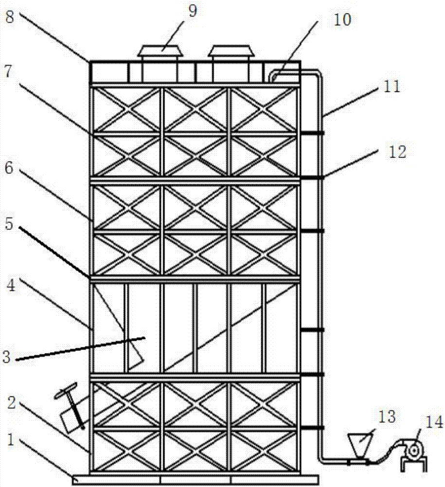
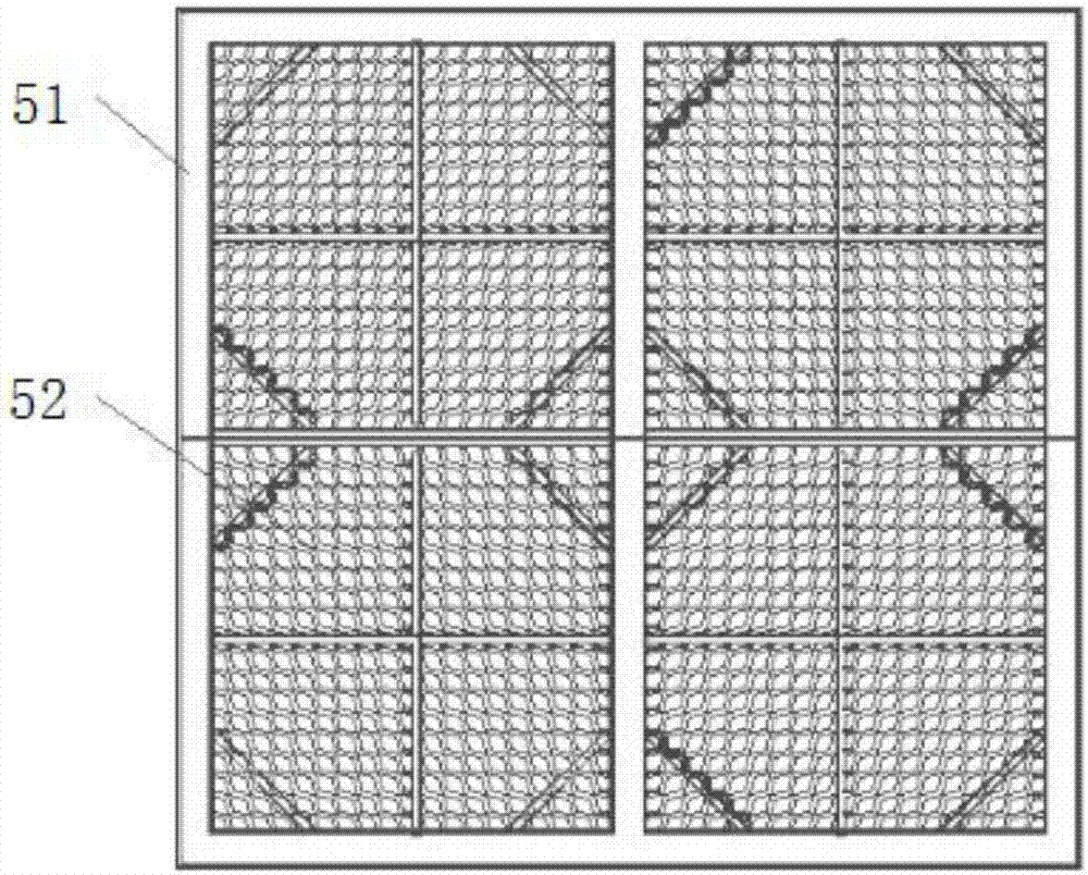
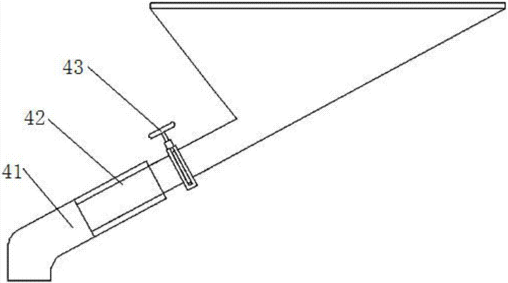
[0036] Such as Figure 1-9 As shown, a collapsible sand tank for formation fracturing includes a top layer sand storage tank 7, a second layer sand storage tank 6, and a sand leakage part 4. The main body of the sand leakage part 4 is a sand leakage section 3, and its side is a leakage Sand support, a bottom guardrail 2 is provided under the sand leakage support, and a positioning device 5 is provided between the bottom guardrail 2 and the sand leakage support. The outside of the sand storage tank 6 is wrapped with a layer of folding bracket 12, and the top of the second layer of sand storage tank 6 is connected to the top layer of sand storage tank 7 through a positioning device 5, and the outside of the top layer of sand storage tank 7 is also wrapped with a layer of folding bracket 12. The inner sides of the folding brackets 12 of the tank 7 and the...


PUM


Abstract

The invention discloses a folding sand tank used for stratum fracturing. The folding sand tank comprises a top layer sand storage tank portion, a second layer sand storage tank portion and a sand leaking portion. The sand leaking portion is internally provided with a sand leaking section. The side surface of the sand leaking portion is provided with a sand leaking support. A bottom protective fence is arranged under the sand leaking support. A positioning device is arranged between the bottom protective fence and the sand leaking support. The upper portion of the sand leaking portion is connected to the second layer sand storage tank portion through the positioning device. The outer side of the second layer sand storage tank portion is wrapped with a layer of a folding support. The upper portion of the second layer sand storage tank portion is connected to the top layer sand storage tank portion through the positioning device. The outer side of the top layer sand storage tank portion is also wrapped with a layer of a folding support. Wallboards are arranged on the inner sides of the folding supports of the top layer sand storage tank portion and the second layer sand storage tank portion correspondingly. A base is arranged under the bottom protective fence. A sand outlet extending obliquely downwards is formed in the sand leaking section. The outer side of the tail end of the sand outlet is sleeved with a telescopic pipe. According to the folding sand tank, the space can be saved, raised dust is reduced, dismounting is convenient, and the transporting and using effects of site fracturing can be effectively improved.

Description

technical field [0001] The invention relates to the technical field of oil and gas field development, in particular to a foldable sand tank for formation fracturing. Background technique [0002] In oil and gas field stimulation operations, low-permeability oil and gas fields, especially shale gas fields, are generally exploited through fracturing to achieve economical and effective development of low-permeability reservoirs. Fracturing is to use the surface high-pressure pump group to pump fracturing fluid into the wellbore to hold up the high pressure to rupture the reservoir, and continue to pump the fracturing fluid through the wellbore to make the fractures formed in the reservoir continue to extend. The fracturing fluid squeezes into the fractures formed in the reservoir, supports the formed fractures, and provides a flow channel with high conductivity for oil and gas, thereby increasing oil and gas production. [0003] At present, the sand tanks used in fracturing co...

Claims


Application Information

Patent Timeline
Patent Type & Authority Applications(China)
IPC IPC(8): B65D6/08B65D6/18B65D25/00E21B43/26
CPCE21B43/26B65D11/14B65D11/1826B65D25/00
Inventor 汤树林
Owner 汤志翔
Why Eureka
Try Eureka