Gas-liquid-solid three-phase abrasive flow plane polishing system based on cavitation effect

A technology of cavitation effect and abrasive flow, which is applied in the direction of used abrasive processing devices, abrasives, abrasive jet machine tools, etc., can solve the problem of three-phase abrasive flow polishing efficiency improvement effect is not obvious, three-phase abrasive flow processing Low efficiency, uneven removal amount on the processed surface, etc., to achieve the effect of improving polishing efficiency, high material removal rate, and increasing the probability of bubble collapse

Active Publication Date: 2018-04-06
ZHEJIANG UNIV OF TECH
View PDF9 Cites 8 Cited by
  • Summary
  • Abstract
  • Description
  • Claims
  • Application Information

AI Technical Summary

Problems solved by technology

[0006] The purpose of the present invention is to solve the shortcomings of the above-mentioned existing three-phase abrasive flow polishing efficiency, such as the inconspicuous effect of improving the polishing efficiency, uneven removal of the processed surface, or high cost, and proposes a gas-liquid-solid three-phase abrasive flow plane based on the cavitation effect. The polishing system uses external mixed gas and structural cavitation gas to collide together to generate micro jets to drive abrasive particles to hit the workpiece. On the basis of not increasing the processing cost, the structure of the polishing tool is changed to improve the low processing efficiency of the existing three-phase abrasive flow and The problem of uneven polishing removal amount improves the processing efficiency and processing effect, realizes high-efficiency and high-quality processing of large-plane workpieces, and achieves the consistency of removal amount in the circumferential direction of workpiece processing by changing the flow channel structure

Method used


Image

  • Gas-liquid-solid three-phase abrasive flow plane polishing system based on cavitation effect
  • Gas-liquid-solid three-phase abrasive flow plane polishing system based on cavitation effect
  • Gas-liquid-solid three-phase abrasive flow plane polishing system based on cavitation effect

Examples


Embodiment Construction

[0042] The present invention will be further described below in conjunction with accompanying drawing:

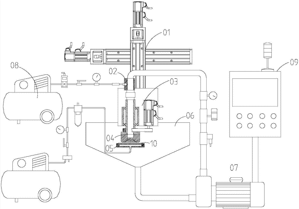
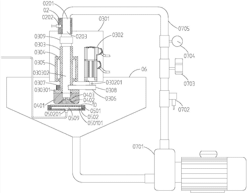
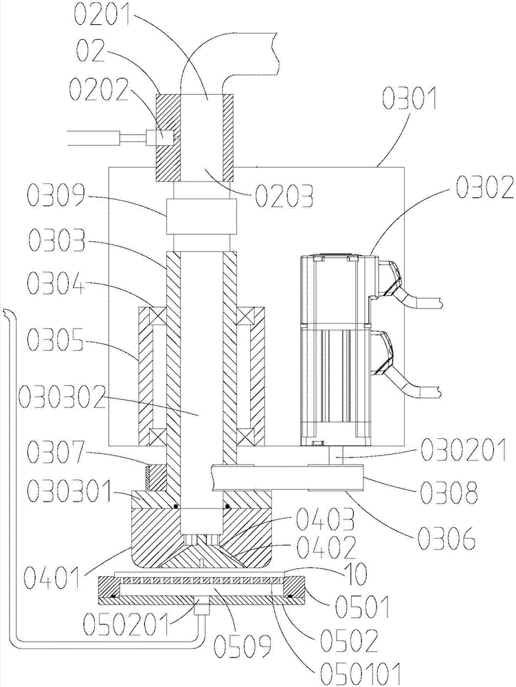
[0043] Such as Figure 1~6 As shown, a gas-liquid-solid three-phase abrasive flow planar polishing system based on the cavitation effect includes a two-degree-of-freedom moving device 01, a gas-liquid-solid mixing device 02, a rotating drive device 03, a cavitation polishing tool 04, and a workpiece device Clamping device 05, workpiece processing pool 06, abrasive particle flow circulation device 07, high-pressure gas injection device 08 and console 09, the rotary drive device 03 is installed on the two-degree-of-freedom mobile device 01, and when the two-degree-of-freedom mobile device 01 moves Drive the rotary drive device 03 to move linearly in both horizontal and vertical directions; the gas-liquid-solid mixing device 02 is installed on the mounting base 0301 of the rotary drive device 03, and the rotating end of the rotary drive device 03 is connected to the cavitation...


PUM


Abstract

The invention discloses a gas-liquid-solid three-phase abrasive flow plane polishing system based on a cavitation effect, comprising a two-degree-of-freedom moving device, a gas-liquid-solid mixing device, a rotary driving device, a cavitation polishing tool, a workpiece clamping device, a workpiece processing pool, an abrasive flow circulation device, a high-pressure gas injection device and a console, wherein the cavitation polishing tool comprises an outer constraint block and an inner constraint block which jointly form an annular narrow-slit flow channel with a large inlet and a small outlet; and the annular narrow-slit flow channel communicates with a through hole in a rotary spindle through an internal flow channel in an outer constraint body. The gas-liquid-solid three-phase abrasive flow plane polishing system based on a cavitation effect uses the principle of structural cavitation to set the annular narrow-slit flow channel on a cavitation polishing tool, and realizes the structural cavitation of the liquid by using a flow channel design with a larger inlet and a smaller outlet, and realizes the high-efficient material removal rate of the workpiece surface; and the liquidsecondary cavitation is realized by the design of a round corner on the cavitation polishing tool, so that the efficiency of fluid polishing is improved.

Description

technical field [0001] The invention relates to the technical field of ultra-precision polishing, and more specifically, to a gas-liquid-solid three-phase abrasive particle flow planar polishing system based on cavitation effect. Background technique [0002] With the development of electronic information technology, precise and ultra-precise optical and semiconductor components are used more and more. It is becoming more and more important to achieve efficient ultra-smooth processing of the surface of optical materials and semiconductor materials. [0003] As an emerging polishing method, liquid polishing is gradually applied to the processing of optical materials and semiconductor materials due to the characteristics of no subsurface damage and low surface roughness during processing. However, the inherent defects of low liquid polishing efficiency are extremely limited. The actual use of liquid polishing is hindered, making it difficult to popularize liquid polishing tec...

Claims


Application Information

Patent Timeline
Patent Type & Authority Applications(China)
IPC IPC(8): B24C3/02B24C7/00B24C9/00
CPCB24C3/02B24C7/0046B24C7/0053B24C9/00Y02P70/10
Inventor 计时鸣潘烨曹慧强谭大鹏
Owner ZHEJIANG UNIV OF TECH
Why Eureka
Try Eureka