
NFC antenna power taking device

A technology of a power taking device and an antenna, applied in the field of communication, can solve the problem that the capacity of the energy storage module affects the normal NFC communication, etc.

Active Publication Date: 2018-04-03
SHENZHEN EXCELSECU DATA TECH
View PDF4 Cites 4 Cited by
  • Summary
  • Abstract
  • Description
  • Claims
  • Application Information

AI Technical Summary

Problems solved by technology

[0005] The present invention provides an NFC antenna power-taking device, which aims to solve the problem that the existing NFC antenna power-taking device has a large capacity of the energy storage module, which will affect the normal NFC communication.

Method used


Image

  • NFC antenna power taking device
  • NFC antenna power taking device
  • NFC antenna power taking device

Examples


Embodiment Construction

[0016] In order to make the object, technical solution and advantages of the present invention clearer, the implementation manner of the present invention will be further described in detail below in conjunction with the accompanying drawings.

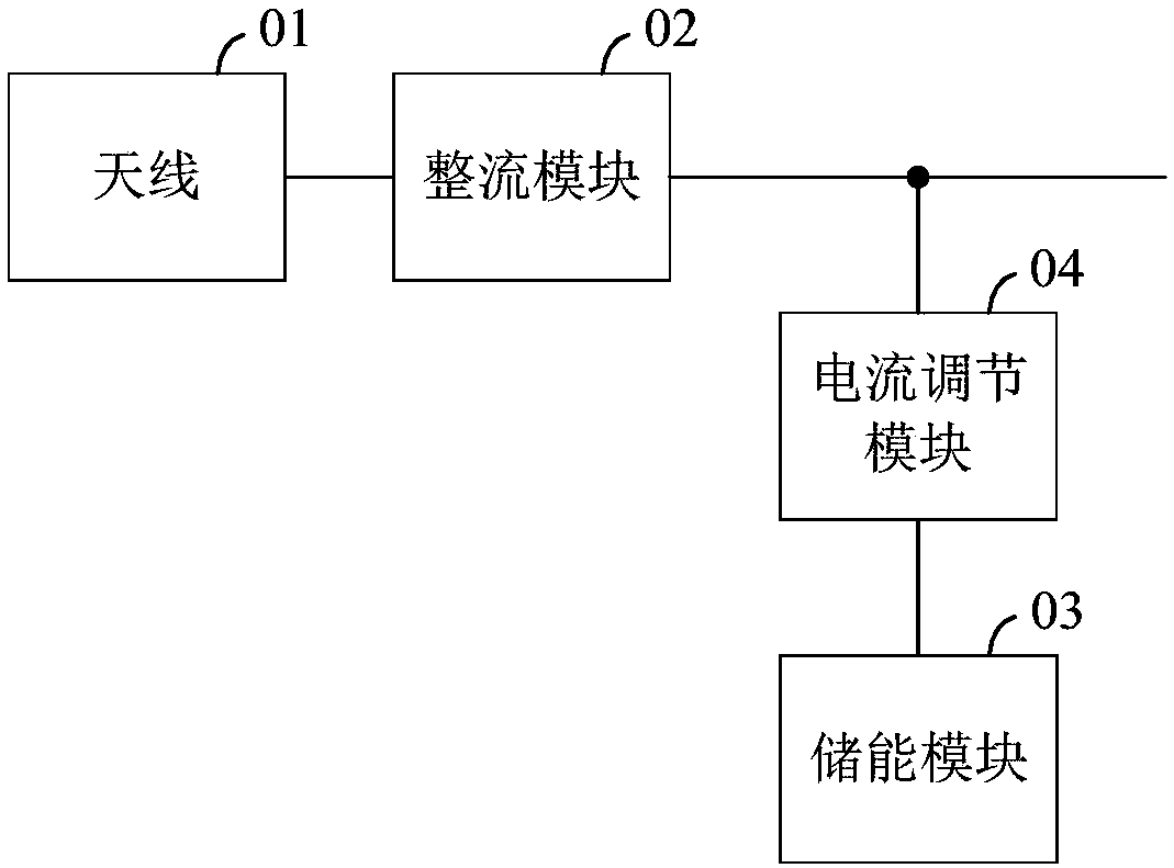
[0017] figure 1 The overall structure of the NFC antenna power-taking device provided by an embodiment of the present invention is shown. For the convenience of description, only the parts related to the embodiment of the present invention are shown, and the details are as follows:

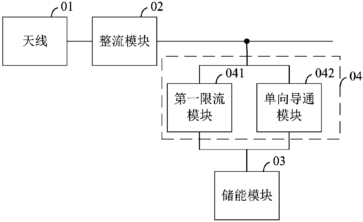
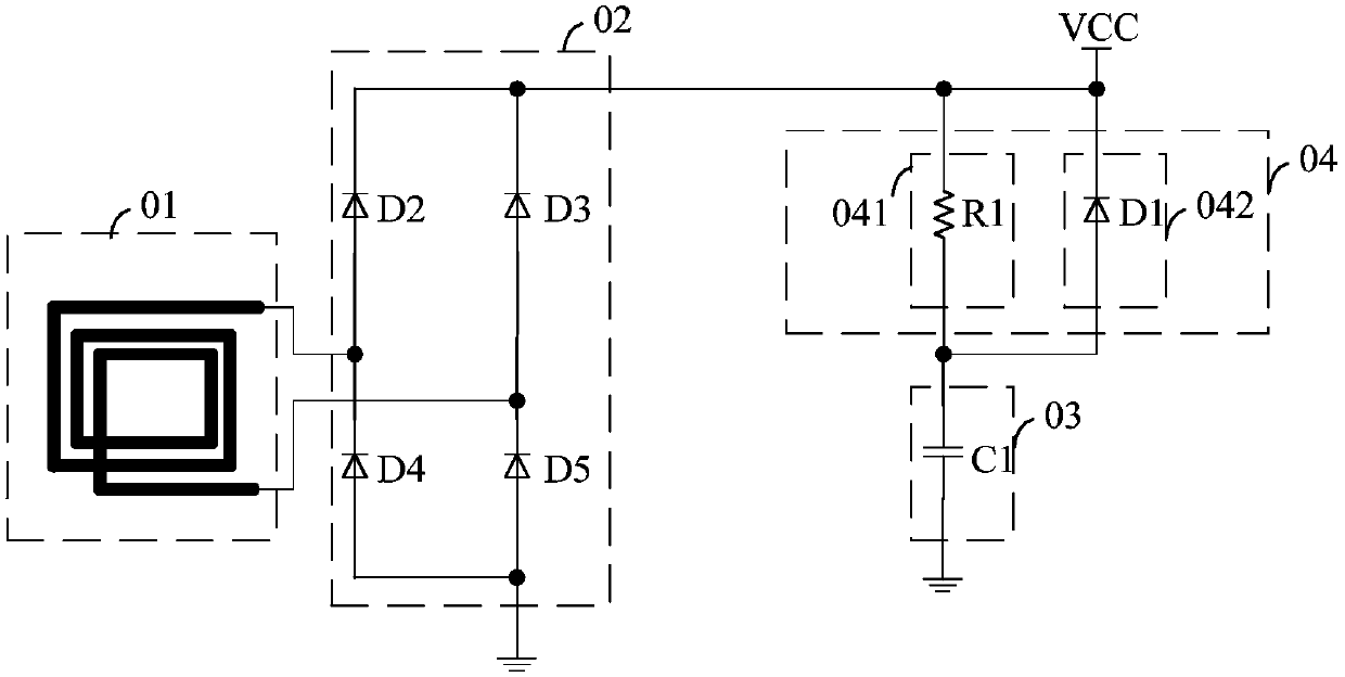
[0018] The NFC antenna power-taking device includes an antenna 01, a rectifier module 02, an energy storage module 03 and a current regulation module 04;

[0019] Wherein, the first feeding end of the antenna 01 is connected to the first input end of the rectifying module 02, the second feeding end of the antenna 01 is connected to the second input end of the rectifying module 02, and the output end of the rectifying module 02 is connected to the current r...


PUM


Abstract

The invention belongs to the technical field of communication, and discloses an NFC antenna power taking device comprising an antenna, a rectifying module, an energy storage module and a current adjusting module; the antenna converts a received electromagnetic energy into a first voltage, the rectifying module rectifies the first voltage to obtain a second voltage, the second voltage charges the energy storage module through the current adjusting module, the current adjusting module adjusts a charging current, when the second voltage is in the tendency of becoming weak because of reduction ofan electromagnetic field, the energy storage module maintains a power supply stable through discharging outwards so as to guarantee regular work of circuits; so, while a relatively large-capacity energy storage module is used, a problem of too much load in an NFC field caused by that the energy storage module obtains too much energy at the moment when an NFC device enters the field is avoided, thus, the NFC device is enabled to perform regular communication and can be identified by an NFC reader and keep steady work.

Description

technical field [0001] The invention belongs to the field of communication, and in particular relates to an NFC antenna power-taking device. Background technique [0002] In the existing antenna power-taking device, the antenna converts the received electromagnetic field energy into a first voltage, and the rectifier module rectifies the first voltage to obtain a second voltage, and the second voltage directly charges the energy storage module. When the second voltage is lower than the voltage of the energy storage module, the energy storage module maintains the stability of the power supply by external discharge to ensure the normal operation of the circuit. [0003] In the existing antenna power-taking device, when the capacity of the energy storage module is small, it cannot provide a good filtering effect, and when the system load is heavy, the energy storage module cannot provide a large instantaneous output, resulting in unstable system operation . In addition, when ...

Claims


Application Information

Patent Timeline
Patent Type & Authority Applications(China)
IPC IPC(8): H02J50/27H04B5/48
CPCH02J50/27H02J50/10H02J7/345H02J7/00712H02J2207/50H02J50/00
Inventor 陈柳章
Owner SHENZHEN EXCELSECU DATA TECH
Learn More