Cooling system for electromagnetic coil

An electromagnetic coil and cooling system technology, applied in the direction of transformer/inductor cooling, transformer/inductor coil/winding/connection, circuit, etc., can solve the problems of reducing magnetic field strength, poor cooling effect, increasing coil resistance, etc., to achieve improvement Cooling efficiency, the effect of improving the cooling effect

Pending Publication Date: 2018-04-03
GUANGDONG HI 1 NEW MATERIALS TECH RES INST CO LTD
View PDF2 Cites 0 Cited by
  • Summary
  • Abstract
  • Description
  • Claims
  • Application Information

AI Technical Summary

Problems solved by technology

[0002] At present, the electromagnetic coil will generate a magnetic field when it is energized, and it will also generate heat while generating the magnetic field, especially when the electromagnetic coil is applied to a strong magnetic field repeating frequency magnet in the laser-driven proton medical range, a single energization load can Generate a strong magnetic field above 10T, but due to the existence of electromagnetic coil resistance, strong current and dense winding are required to generate a strong magnetic field, so the electromagnetic coil will also generate a large amount of Joule heat while generating a strong magnetic field. If the heat is not Timely discharge will increase the temperature of the coil and increase the resistance of the coil. When the next load is applied, more heat will be generated and the strength of the magnetic field will be reduced. Therefore, these heat must be discharged
At present, the electromagnetic coil is mainly cooled by immersing it in insulating cooling liquid, but the cooling effect is poor, so it is far from meeting the needs of the industry.

Method used


Image

  • Cooling system for electromagnetic coil
  • Cooling system for electromagnetic coil
  • Cooling system for electromagnetic coil

Examples


Embodiment Construction

[0021] Below, the present invention will be further described in conjunction with the accompanying drawings and specific implementation methods. It should be noted that, under the premise of not conflicting, the various embodiments described below or the technical features can be combined arbitrarily to form new embodiments. .

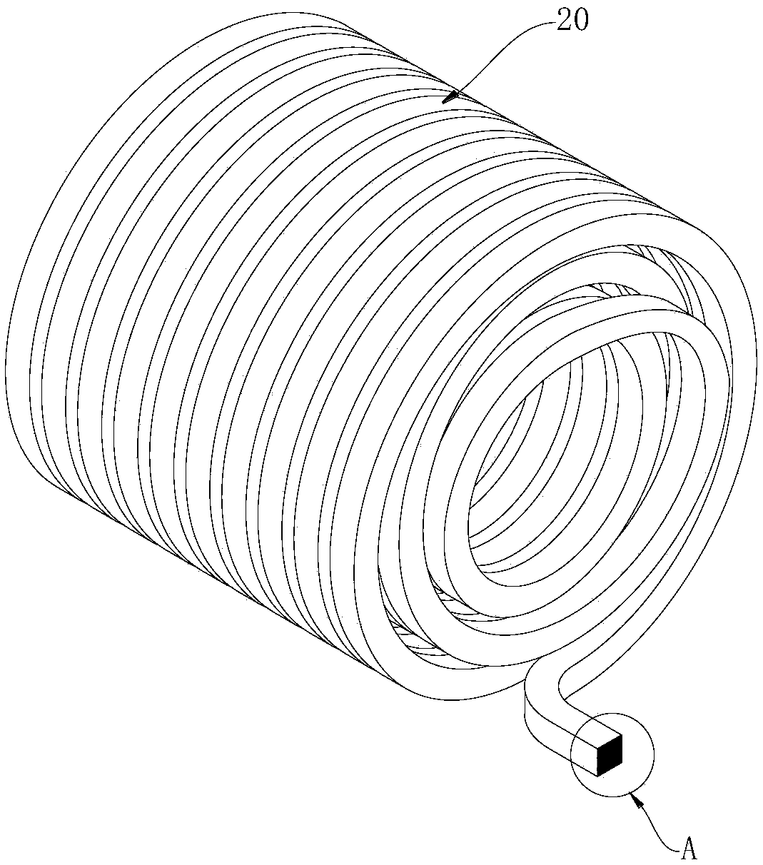
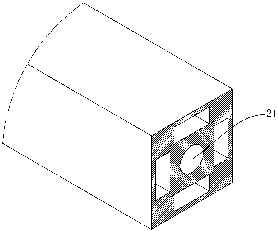
[0022] Such as figure 1 An electromagnetic coil cooling system shown includes a liquid storage tank 10 for holding an external insulating cooling liquid, an electromagnetic coil cooling pipeline for flowing through the built-in insulating cooling liquid, and a circuit for driving the built-in insulating cooling liquid. The liquid driving device 50 that flows to make the built-in insulating cooling liquid flow through the electromagnetic coil cooling pipeline; the electromagnetic coil cooling pipeline includes the electromagnetic coil 20 located in the liquid storage tank 10 and used to be immersed in the external insulating cooling liquid, the first ra...


PUM


Abstract

The invention discloses a cooling system for an electromagnetic coil. The cooling system comprises a liquid storage tank for containing an external insulating coolant, an electromagnetic coil coolingpipe through which an internal insulating coolant flows, and a liquid drive device, wherein the electromagnetic coil cooling pipe comprises the electromagnetic coil which is located in the liquid storage tank and used for being immersed into the external insulating coolant, a first radiator and a second radiator; a cooling channel through which the internal insulating coolant flows is arranged inthe electromagnetic coil; the liquid drive device comprises a hydraulic cylinder, a vacuum tank and an evacuating device for evacuating the vacuum tank; a liquid inlet, a liquid outlet and an air outlet are formed in the vacuum tank; and one end of the electromagnetic coil cooling pipe is formed as a first end and communicates with the liquid outlet of the hydraulic cylinder. According to the cooling system, the cooling effect on the electromagnetic coil can be improved.

Description

technical field [0001] The invention relates to the field of electromagnetic coil cooling, in particular to an electromagnetic coil cooling system. Background technique [0002] At present, the electromagnetic coil will generate a magnetic field when it is energized, and it will also generate heat while generating the magnetic field, especially when the electromagnetic coil is applied to a strong magnetic field repeating frequency magnet in the laser-driven proton medical range, a single energization load can Generate a strong magnetic field above 10T, but due to the existence of electromagnetic coil resistance, strong current and dense winding are required to generate a strong magnetic field, so the electromagnetic coil will also generate a large amount of Joule heat while generating a strong magnetic field. If the heat is not Discharging in time will increase the temperature of the coil and increase the resistance of the coil. When the next load is applied, more heat will ...

Claims


Application Information

Patent Timeline
Patent Type & Authority Applications(China)
IPC IPC(8): H01F27/28H01F27/10H01F27/32
CPCH01F27/10H01F27/2876H01F27/322
Inventor 王伟王毅史忠山向军吕松浩
Owner GUANGDONG HI 1 NEW MATERIALS TECH RES INST CO LTD
Why Eureka
Try Eureka