


Quick Research
Generate reliable direction feasibility study reports for your R&D in just a few steps.

Technical Q&A
Discover and master advanced knowledge NOW. Basics, ideas, possibilities, all at once.

Find Solutions
As an expert in R&D theories, this can generate solutions to your technical problems instantly.

Evaluate Feasibility
Analyze your overall solution with one click, know your potential R&D risks in advance.

Monitor Landscape
Get weekly tech updates, stay abreast of the latest tech innovations and key insights.
Motor heat dissipation structure, motor with motor heat dissipation structure and heat dissipation method
A technology of motor heat dissipation and heat dissipation grooves, which is applied in the field of motors and can solve problems such as the inability to effectively cool down the motor
- Summary
- Abstract
- Description
- Claims
- Application Information
AI Technical Summary
Problems solved by technology
Method used
Image

Examples
Embodiment 1
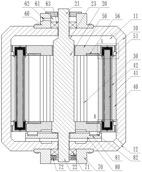
[0046] A motor heat dissipation structure, such as figure 1 As shown, it includes a casing 10 , a rotating shaft 20 , a rotor 30 and a stator 40 are arranged inside the casing 10 , the rotating shaft 20 is rotatably connected with the casing 10 , the rotor 30 is fixed on the rotating shaft 20 , and the stator 40 is fixed on the inner wall of the casing 10 The rotor 30 is arranged with a permanent magnet, the stator 40 is arranged with a coil 41 , a cooling disk 50 is arranged between the stator 40 and the rotating shaft 20 , and the cooling disk 50 is distributed at the upper and lower ends of the stator 40 .
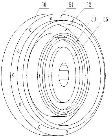
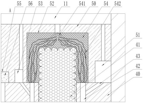
[0047] like Figure 1-4 As shown, the heat dissipation plate 50 divides the space between the rotating shaft 20 and the inner wall of the casing 10 into a liquid cavity 11, an outer heat dissipation groove 51, a resin ring groove 52 and an inner heat dissipation groove 53. The liquid cavity 11 communicates with the outer heat dissipation groove 51 and the inner heat dis...
Embodiment 2
[0068] A motor heat dissipation structure, such as Image 6 As shown, it includes a casing 10 , a rotating shaft 20 , a rotor 30 and a stator 40 are arranged inside the casing 10 , the rotating shaft 20 is rotatably connected with the casing 10 , the rotor 30 is fixed on the rotating shaft 20 , and the stator 40 is fixed on the inner wall of the casing 10 The rotor 30 is arranged with a permanent magnet, the stator 40 is arranged with a coil 41 , a cooling disk 50 is arranged between the stator 40 and the rotating shaft 20 , and the cooling disk 50 is distributed at the upper and lower ends of the stator 40 .
[0069] An upper magnet unit 91 and a lower magnet unit 92 are arranged between the inner bottom of the casing 10 and the heat dissipation plate 50 .
[0070] A support structure is usually arranged between the rotating shaft 20 and the inner bottom of the casing 10, but the high-speed rotation of the rotating shaft 20 will generate a lot of heat due to friction with the...
Embodiment 3
[0074] A motor, the motor has the motor heat dissipation structure in the first or second embodiment. A hydraulic pump, a filter, a heat exchanger, and an oil tank are communicated between the liquid discharge port 12 on the inner bottom side of the casing 10 and the liquid inlet port 62 of the upper bearing seat 60 . After the cooling liquid is discharged from the liquid discharge port 12, it is transported by the hydraulic pump to the filter and the heat exchanger, and then flows into the oil tank, and then enters the liquid inlet port 62 from the oil tank for reuse to realize circulating cooling.
PUM
| Property | Measurement | Unit |
|---|---|---|
| Thermal conductivity | aaaaa | aaaaa |
| Thermal conductivity | aaaaa | aaaaa |
Abstract
Description
Claims
Application Information
 - R&D Engineer
- R&D Manager
- IP Professional
- Industry Leading Data Capabilities
- Powerful AI technology
- Patent DNA Extraction
Browse by: Latest US Patents, China's latest patents, Technical Efficacy Thesaurus, Application Domain, Technology Topic, Popular Technical Reports.
© 2024 PatSnap. All rights reserved.Legal|Privacy policy|Modern Slavery Act Transparency Statement|Sitemap|About US| Contact US: help@patsnap.com