


Quick Research
Generate reliable direction feasibility study reports for your R&D in just a few steps.

Technical Q&A
Discover and master advanced knowledge NOW. Basics, ideas, possibilities, all at once.

Find Solutions
As an expert in R&D theories, this can generate solutions to your technical problems instantly.

Evaluate Feasibility
Analyze your overall solution with one click, know your potential R&D risks in advance.

Monitor Landscape
Get weekly tech updates, stay abreast of the latest tech innovations and key insights.
A thermal pressure sensor
A pressure sensor and thermal sensor technology, applied in the field of sensors, can solve the problems of high sensitivity and upper limit of the use range, limited work of squeezing air, and small deformation, etc., to achieve the effect of expanding the scope of application
- Summary
- Abstract
- Description
- Claims
- Application Information
AI Technical Summary
Problems solved by technology
Method used
Image

Examples
Embodiment Construction
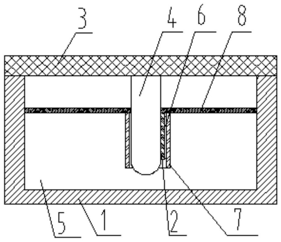
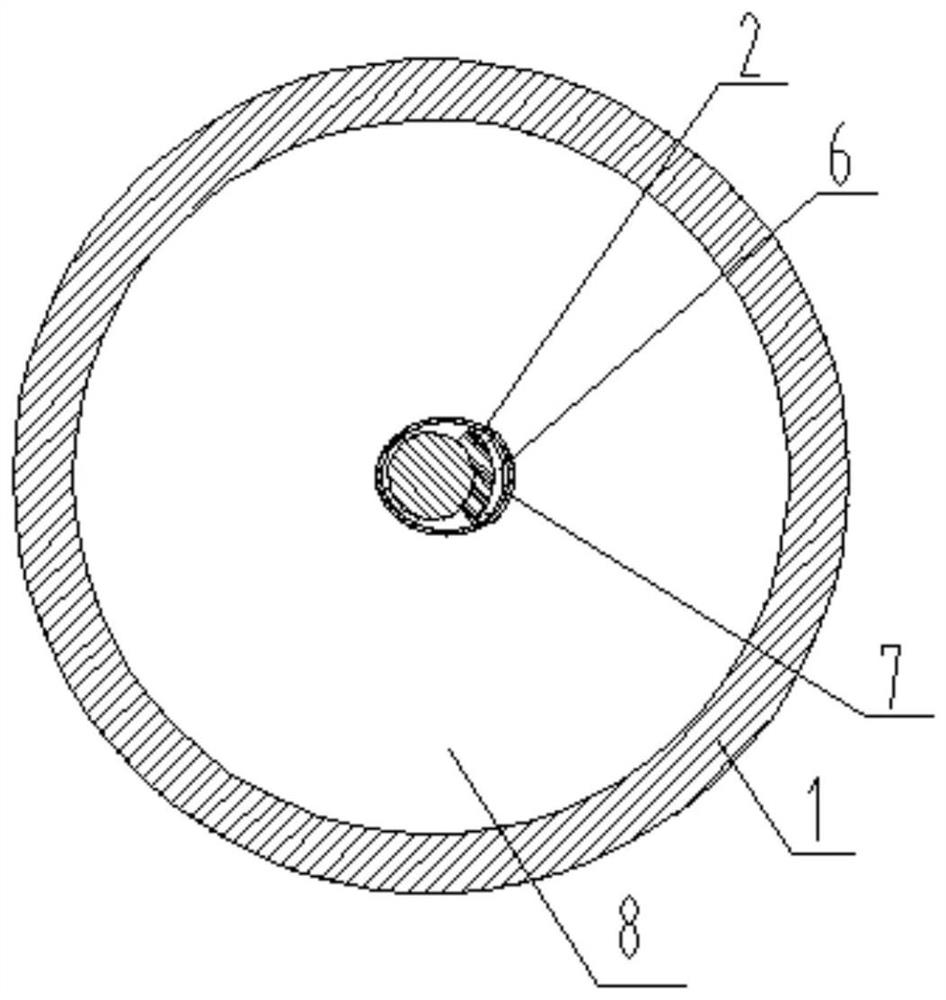
[0018] Reference figure 1 , figure 2 , A thermal pressure sensor proposed by the present invention includes: a base 1, a thermal conductor 2, an elastic cover 3 and a friction column 4.
[0019] The base 1 is provided with a heat-resistant cavity 5 with an open top, and the thermal conductor 2 is installed on the base 1 and is located in the heat-resistant cavity 5. The elastic cover 3 is installed on the base 1 and covers the opening of the heat-resisting cavity 5. By matching the elastic cover 3 and the base 1, the heat-resisting cavity 5 forms a sealed cavity to delay the heat loss in the heat-resisting cavity 5 . In this embodiment, the inner wall of the heat resistance cavity 5 is coated with a heat insulation layer to further improve the heat retention ability of the heat resistance cavity 5.
[0020] The friction column 4 is installed on the elastic cover 3 and inserted into the heat-resistant cavity 5. The thermal conductor 2 abuts against the side wall of the friction ...
PUM
 Abstract
Description
Claims
Application Information
 - R&D Engineer
- R&D Manager
- IP Professional
- Industry Leading Data Capabilities
- Powerful AI technology
- Patent DNA Extraction
Browse by: Latest US Patents, China's latest patents, Technical Efficacy Thesaurus, Application Domain, Technology Topic, Popular Technical Reports.
© 2024 PatSnap. All rights reserved.Legal|Privacy policy|Modern Slavery Act Transparency Statement|Sitemap|About US| Contact US: help@patsnap.com