
Thermal environment control structure and method for fused deposition process of 3D printer

A 3D printer, fused deposition technology, applied in 3D object support structure, processing environment adjustment, additive manufacturing, etc., can solve the problems of reduced service life and reliability, bulky insulation cabin structure, high temperature aging, etc., to control the bond strength. and deformation degree, good thermal environment control effect, and low comprehensive energy consumption

Pending Publication Date: 2018-04-03
杭州德迪智能科技有限公司
View PDF0 Cites 4 Cited by
  • Summary
  • Abstract
  • Description
  • Claims
  • Application Information

AI Technical Summary

Problems solved by technology

However, the thermal insulation cabin is not only heavy in structure, high in energy consumption, and high in cost, but also easily causes high-temperature aging of servo devices, electrical sensors, and signal lines in the cabin, reducing its service life and reliability
At present, in the field of FDM 3D printers, there is still a lack of a thermal environment control method that can efficiently control the thermal environment of the fusion deposition process, and does not require real-time sealing and insulation of the entire cabin environment.

Method used


Image

  • Thermal environment control structure and method for fused deposition process of 3D printer
  • Thermal environment control structure and method for fused deposition process of 3D printer
  • Thermal environment control structure and method for fused deposition process of 3D printer

Examples


Embodiment Construction

[0019] The present invention will be further described below in conjunction with accompanying drawing:

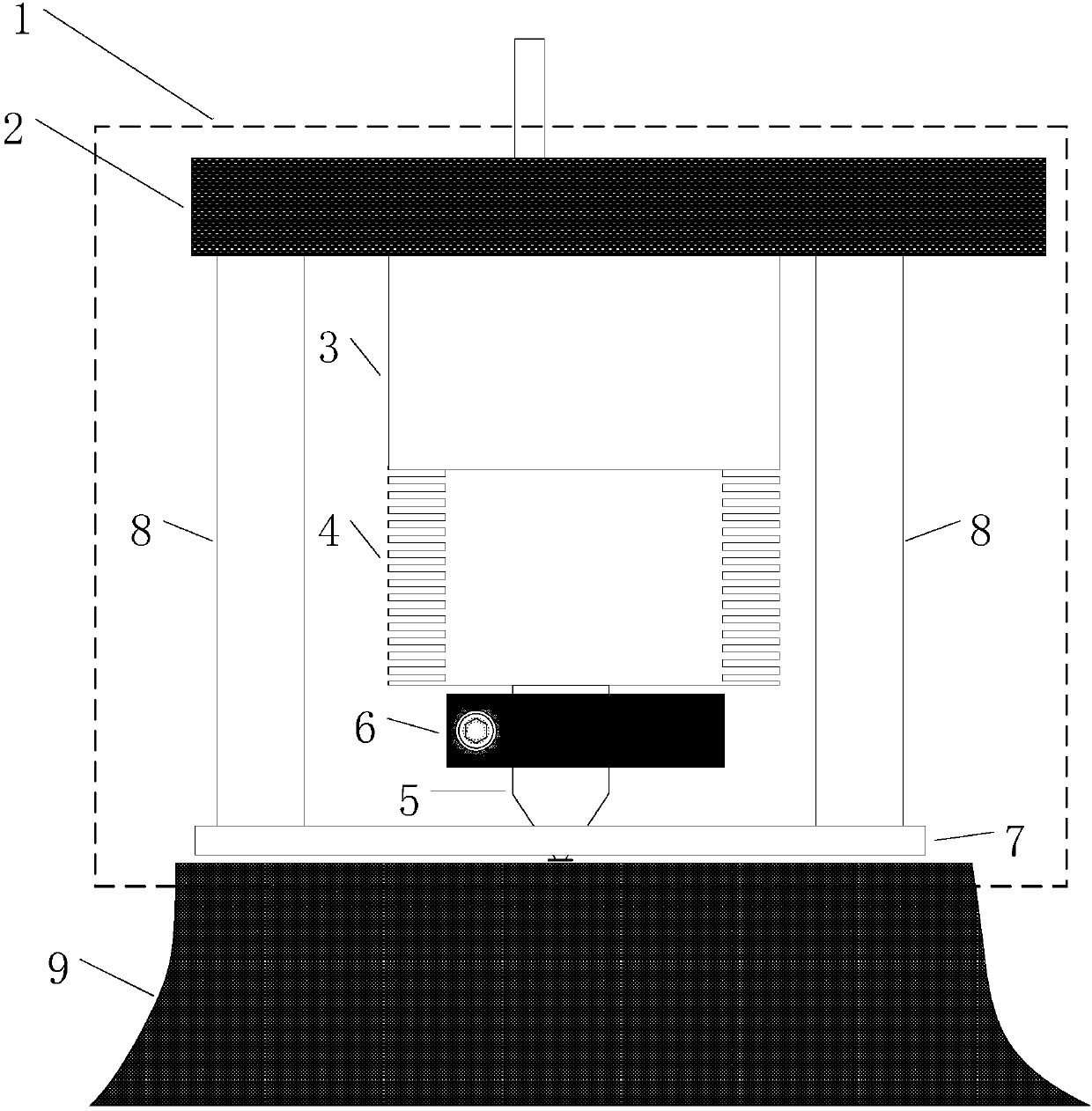
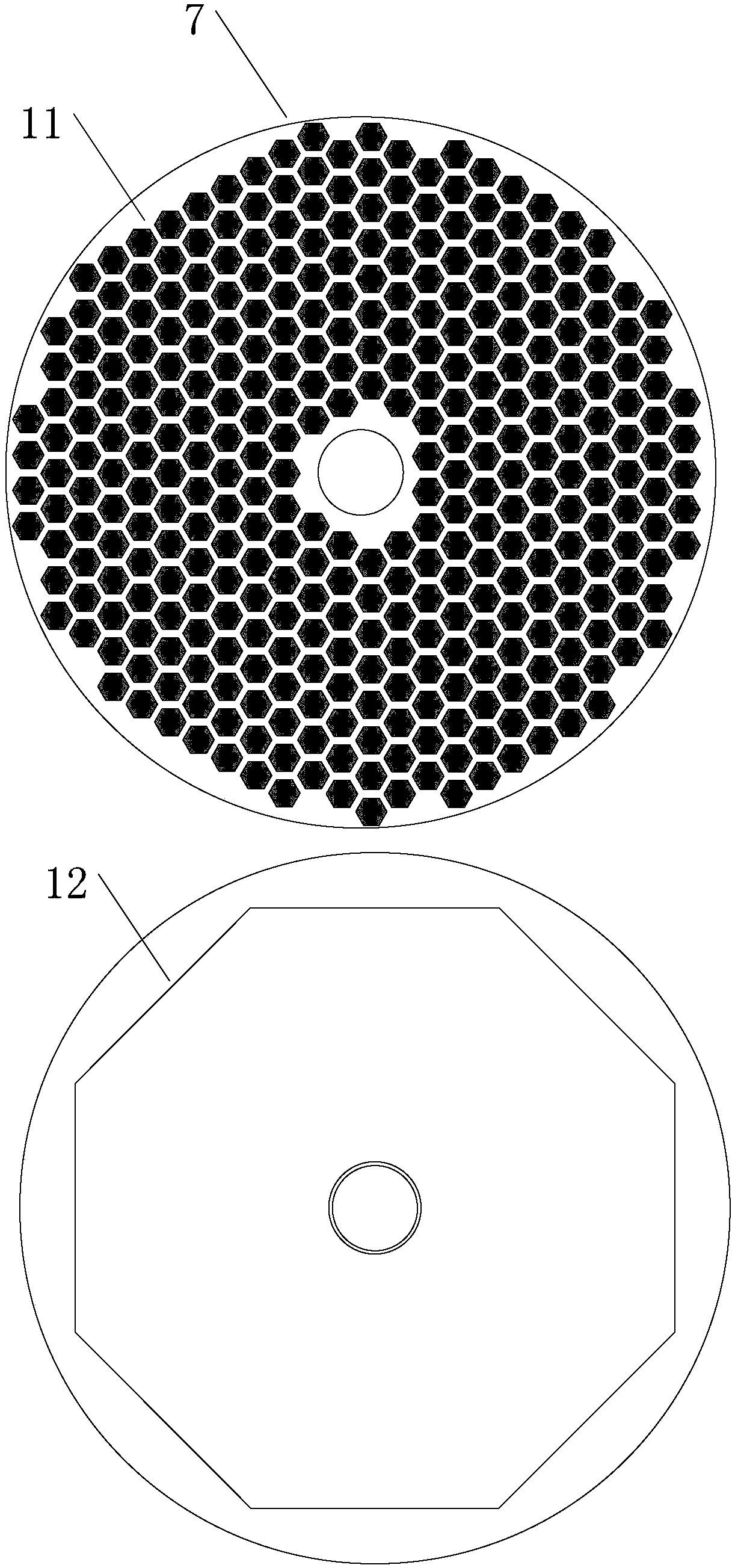
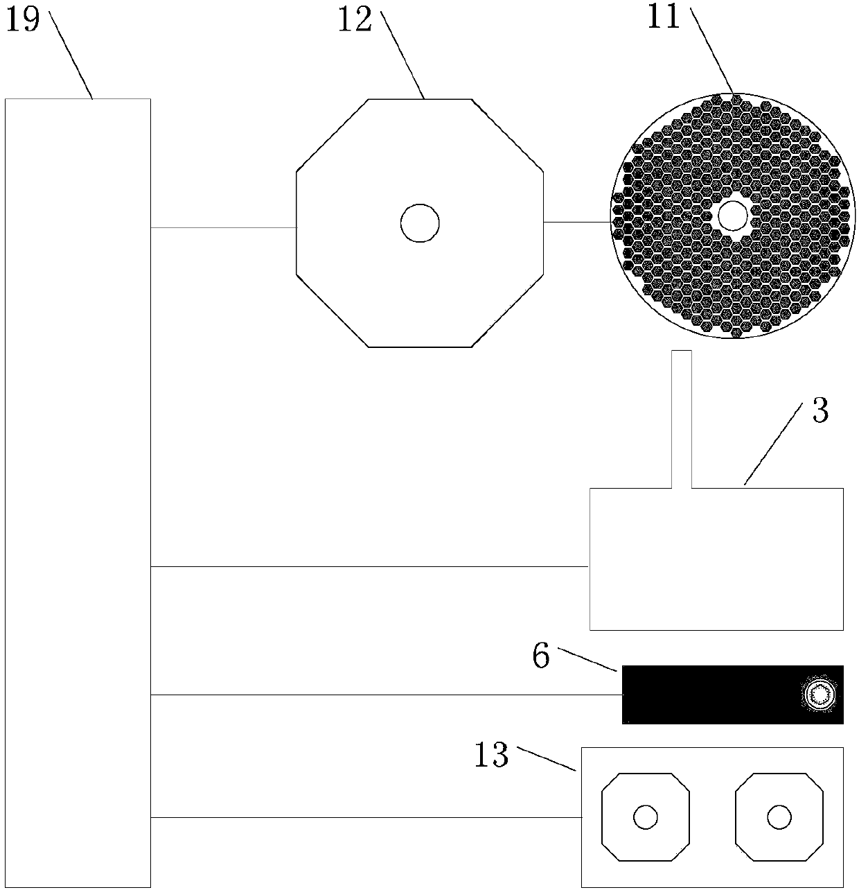
[0020] figure 1 Among them, there is a base 2 in the melting extrusion head 1, the base 2 is connected with the servo wire feeding mechanism 3, the servo wire feeding mechanism 3 is connected with the heat dissipation guide tube 4, the heat dissipation guide tube 4 is connected with the high temperature extrusion head 5, and the high temperature extrusion There is a constant temperature heating block 6 on the head 5, and the ring-shaped light-emitting board 7 is connected to the base 2 through a bracket 8. The center of the ring-shaped light-emitting board 7 is aligned with the axis of the high-temperature extrusion head 5. The center passes through the annular luminous plate 7, and there is a slight height difference between the tip of the high-temperature extrusion head 5 and the lower surface of the annular luminous plate 7, so that when the tip of the high-temperature e...


PUM


Abstract

The invention relates to a thermal environment control structure and method for a fused deposition process of a 3D printer. The thermal environment control structure comprises a 3D printing controller, and a melted extruding head, wherein a base is arranged in the melted extruding head, a servo wire feeding mechanism is connected to the base, the servo wire feeding mechanism is connected to a high-temperature extruding head through heat radiation and heat conduction wires, and a thermostatic heating block is arranged on the high-temperature extruding head, an annular light emitting plate is connected with the base through supports, the high-temperature extruding head extends out of the annular light emitting plate, the end of the high-temperature extruding head is higher than the lower surface of the annular light emitting plate, a thermal radiation luminescent tube array is uniformly distributed on the annular light emitting plate, the thermal radiation luminescent tube array is connected with a thermal radiation controller, and the thermal radiation controller can be used for independent control of each thermal radiation luminescent tube in the thermal radiation luminescent tubearray. The thermal environment control structure and method have the advantages of simple structure, reasonable scheme, good thermal environment control effects of a fused deposition key area, low comprehensive energy consumption, no need of cabin sealing and low cost, and are easy to popularize and apply in the 3D printing industry.

Description

technical field [0001] The invention relates to the field of 3D printers, in particular to a thermal environment control structure and method for the fusion deposition process of a 3D printer. Background technique [0002] Fused Deposition Modeling (FDM) 3D printers are currently one of the most widely used types of 3D printers. It provides a low-cost and rapid processing method for 3D parts without molds. 3D printers using FDM technology combine resin, engineering Plastic and other plastic wires are melted at high temperature by the melting extrusion head, and then deposited layer by layer on the section of the three-dimensional part according to the numerical control path, and finally accumulate the desired three-dimensional shape. During the fused deposition process, the working chamber of most 3D printers is at room temperature, and only when printing the first few layers, it passes through the hot bed-the substrate with constant temperature heating function, to keep the...

Claims


Application Information

Patent Timeline
Patent Type & Authority Applications(China)
IPC IPC(8): B29C64/118B29C64/20B29C64/364B29C64/393B33Y30/00B33Y40/00B33Y50/02
CPCB33Y30/00B33Y40/00B33Y50/02
Inventor 俞红祥应华
Owner 杭州德迪智能科技有限公司
Learn More