
Decoding method and system for a resolver

A resolver and decoding method technology, applied in the direction of electronic commutator, motor parameter estimation/correction, etc., can solve the problems of high cost, many external circuits, and no relative advantage in price hardware decoding, etc., to achieve cost reduction and reasonable The effect of the design

Inactive Publication Date: 2019-07-16
CHENGDU RAJA NEW ENERGY AUTOMOTIVE TECH CO LTD
View PDF5 Cites 0 Cited by
  • Summary
  • Abstract
  • Description
  • Claims
  • Application Information

AI Technical Summary

Problems solved by technology

[0009] 1) The cost of using a dedicated hardware decoding chip is relatively high, and the price of a hardware decoding chip is equivalent to the price of a motor controller main control chip;
[0010] 2) The existing software decoding scheme requires external filtering and demodulation, which requires more external circuits, and the entire price has no relative advantage compared with hardware decoding

Method used


Image

  • Decoding method and system for a resolver
  • Decoding method and system for a resolver
  • Decoding method and system for a resolver

Examples


Embodiment Construction

[0066] The technical solution of the present invention will be further described in detail below in conjunction with the accompanying drawings, but the protection scope of the present invention is not limited to the following description.

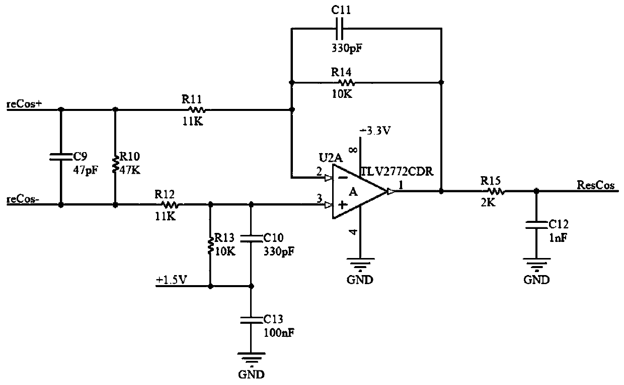
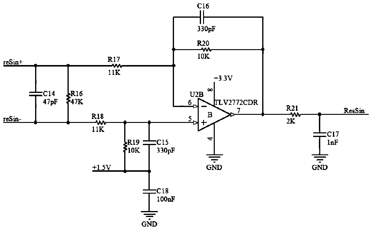
[0067] The resolver is used in the field of motor control as a sensor for the angle and speed of the motor. The resolver is composed of a stator and a rotor, the stator is mounted on the stator of the motor, and the rotor is mounted on the rotor of the motor. Inputting a sinusoidal AC drive voltage on the primary side of the resolver will induce two AC voltage signals, sine and cosine, with the same frequency as the primary side and amplitude changes with the stator and rotor angles on the secondary side. The angle and rotation speed of the rotor of the motor can be calculated through the output signals of sine and cosine. Existing decoding technology solutions generally have high cost. This solution uses software to realize part of the fu...


PUM


Abstract

The invention discloses a decoding method of a rotary transformer, which comprises the following steps: Step 1: device-related initialization configuration, parameter initialization of the rotary transformer; step 2: demodulating and filtering the feedback signal; step 3: calculating the filter of the rotary transformer Step 4: After compensating the resolver angle, calculate the speed; it also includes an interrupt program, which includes the following steps: take the duty cycle of the next PWM waveform and load it into the COMPA of the PWM module register of the main control chip, every In a cycle period, when the value of the internal counter of the PWM is greater than COMPA, the level will be set low, thereby generating a PWM waveform with high and low level changes; sampling the sine and cosine feedback values ​​of the resolver; eliminating the sine and cosine feedback DC component; return to the main loop of the main control chip.

Description

technical field [0001] The invention relates to a decoding method and system for a resolver. Background technique [0002] The resolver is used in the field of motor control as a sensor for the angle and speed of the motor. The resolver is composed of a stator and a rotor, the stator is mounted on the stator of the motor, and the rotor is mounted on the rotor of the motor. Inputting a sinusoidal AC drive voltage on the primary side of the resolver will induce two AC voltage signals, sine and cosine, with the same frequency as the primary side and amplitude changes with the stator and rotor angles on the secondary side. The angle and rotation speed of the rotor of the motor can be calculated through the output signals of sine and cosine. Existing decoding technology solutions generally have high cost. This solution uses software to realize part of the functions of the hardware, and uses the resources of the main control chip to replace the dedicated decoding chip, thereby r...

Claims


Application Information

Patent Timeline
Patent Type & Authority Patents(China)
IPC IPC(8): H02P6/17H02P23/14
CPCH02P6/17H02P23/14
Inventor 廖绍文盛旺余胜陈俊兵何伟
Owner CHENGDU RAJA NEW ENERGY AUTOMOTIVE TECH CO LTD
Learn More