
Image correction method for optical coherence tomography system

A technology of optical coherence tomography and imaging system, which is applied in the field of image correction of optical coherence tomography imaging system. It can solve the problems of OCT system image inconsistency, affecting the measurement of sample physical structure, etc., and achieve the effect of eliminating distortion and eliminating spherical distortion.

Active Publication Date: 2018-03-30
ZHENGZHOU UNIVERSITY OF LIGHT INDUSTRY
View PDF5 Cites 16 Cited by
  • Summary
  • Abstract
  • Description
  • Claims
  • Application Information

AI Technical Summary

Problems solved by technology

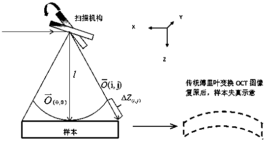
[0004] Aiming at the technical problem that the scanning distortion of the existing technology causes the imaging of the OCT system to be inconsistent with the image of the sample itself, which affects the measurement of the physical structure of the sample, the present invention proposes an image correction method for an optical coherence tomography system.

Method used


Image

  • Image correction method for optical coherence tomography system
  • Image correction method for optical coherence tomography system
  • Image correction method for optical coherence tomography system

Examples


Embodiment Construction

[0027] The following will clearly and completely describe the technical solutions in the embodiments of the present invention with reference to the accompanying drawings in the embodiments of the present invention. Obviously, the described embodiments are only some, not all, embodiments of the present invention. Based on the embodiments of the present invention, all other embodiments obtained by persons of ordinary skill in the art without making creative efforts belong to the protection scope of the present invention.

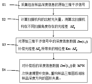
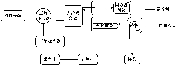
[0028] Such as figure 1 As shown, an image correction method of an optical coherence tomography system includes: obtaining the original three-dimensional interference signal containing sample depth information; performing phase difference compensation on the sample depth information in the original three-dimensional interference signal, and compensating the sample depth information after compensation Perform fast Fourier transform to reconstruct the XYZ three-...


PUM


Abstract

The invention provides an image correction method for an optical coherence tomography system. The image correction method comprises the steps of collecting original three-dimensional interference signals containing depth information of a sample in the OCT (Optical Coherence Tomography) system; calculating an emergent light vector of a scanning mechanism, and measuring and calculating the optical path difference of the scanning mechanism at different scanning angles; compensating the phase difference brought about by the optical path difference for the depth information of the sample in the original three-dimensional interference signals to obtain the compensated depth information of the sample; performing fast Fourier transform on the compensated depth information of the sample, and reconstructing an XYZ three-dimensional diagram of the sample; and removing mirror image information of the XYZ three-dimensional diagram in the Z direction to obtain a recovered XYZ three-dimensional diagram of the sample. According to the invention, phase difference compensation is performed on the depth information data of the sample in the original three-dimensional interference signals, and fast Fourier transform is performed on the compensated depth information of the sample so as to eliminate the image distortion caused in the depth direction of the sample. The image correction method is notrestricted by the structure of the OCT system, and does not affect accurate measurement for the physical structure of the sample.

Description

technical field [0001] The present invention relates to the technical field of optical coherence tomography (OCT for short), in particular to an image correction method for an optical coherence tomography system. Background technique [0002] Optical coherence tomography (OCT) is an emerging technology that has emerged in the past decade. It is based on the principle of light interference and uses a broadband light source to achieve high-resolution depth tomography with a resolution of several microns. OCT can be divided into time domain and frequency domain according to the principle of image processing. Time domain OCT (TDOCT) performs tomographic scanning in the depth direction of the sample by moving the reference arm, while frequency domain OCT (FDOCT) divides the broadband light source into many independent The spectrum is obtained by performing Fourier transform on the finally obtained interference data to complete the depth tomography, so there is no need to move the...

Claims


Application Information

Patent Timeline
Patent Type & Authority Applications(China)
IPC IPC(8): G06T5/00G06T5/10G06T11/00
CPCG06T5/10G06T11/008G06T2207/10101G06T2207/20056G06T5/80
Inventor 王东琳杨坤杨红军郝蕴琦翟凤潇
Owner ZHENGZHOU UNIVERSITY OF LIGHT INDUSTRY
Learn More