Optical synchronous measurement method for combustion flow field of scramjet engine

A technology of scramjet and synchronous measurement, which is used in internal combustion engine testing, measurement devices, aerodynamic tests, etc., can solve the problems of inability to perform supplementary verification, inaccurate flow information acquisition, etc., to improve interactivity and eliminate image distortion. Effect

Inactive Publication Date: 2020-08-25
CHINA AERODYNAMICS RES & DEV CENT
View PDF5 Cites 6 Cited by
  • Summary
  • Abstract
  • Description
  • Claims
  • Application Information

AI Technical Summary

Problems solved by technology

[0003] The present invention intends to provide a scramjet combustion flow field optical synchronous measurement method to solve the problem that the existing combustion flow field diagnosis method is inaccurate in obtaining flow information at the same time and cannot perform supplementary verification

Method used


Image

  • Optical synchronous measurement method for combustion flow field of scramjet engine
  • Optical synchronous measurement method for combustion flow field of scramjet engine
  • Optical synchronous measurement method for combustion flow field of scramjet engine

Examples


Embodiment Construction

[0027] Below in conjunction with accompanying drawing and embodiment the present invention is described in further detail:

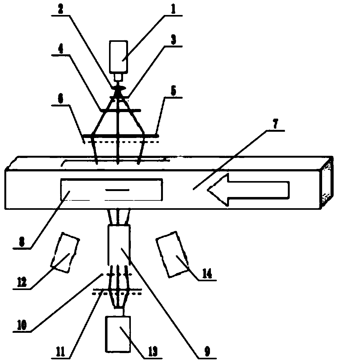
[0028] The reference signs in the drawings of the description include: continuous laser 1, short-focus lens 2, hologram 3, ground glass 4, Fresnel lens 5, source grid 6, scramjet direct-connected test model 7, quartz glass Observation window 8, imaging lens 9, knife-edge grid 10, imaging screen 11, ICCD camera 12, first high-speed camera 13, second high-speed camera 14.

[0029] A scramjet combustion flow field optical synchronous measurement method, which adopts the optical path settings such as figure 2 As shown, the optical path components mainly include: continuous laser 1, short-focus lens 2, hologram 3, ground glass 4, Fresnel lens 5, source grid 6, pulse laser, optical path shaping system, imaging lens 9, knife-edge grid 10, ICCD camera 12 , first high-speed camera 13 and second high-speed camera 14 . The sheet light in the figure is generated...


PUM


Abstract

The invention discloses an optical synchronous measurement method for a combustion flow field of a scramjet engine, and the method comprises the steps: S1, giving an incoming flow condition based on ascramjet engine direct connection type test model; S2, respectively adopting a focusing schlieren technology, a laser-induced fluorescence technology and a self-luminous photograph to obtain flow field structure images of the same section at the same moment in the flow field of the scramjet engine direct connection type test model; S3, correcting the three flow field structure images obtained inthe step S2 through Matlab image processing; and S4, comparing and verifying the three flow field structure images corrected in the step S3. The method can accurately obtain the flow field characteristics in the engine combustion chamber configuration at the same time on the same cross section, improves the interactivity of information obtained by three measurement means, and improves the understanding of the flow and combustion dynamic change characteristics in the engine combustion chamber.

Description

technical field [0001] The invention relates to the field of hypersonic technology, in particular to an optical synchronous measurement method for the combustion flow field of a scramjet engine. Background technique [0002] The scramjet engine is one of the best propulsion devices for hypersonic vehicles. The residence time of high-speed air in the combustion chamber is extremely short, usually on the order of milliseconds. In this extremely short time, fuel injection, mixing, ignition and stable combustion need to be achieved. The existence of a series of extreme problems has brought great challenges to the optimization and design of scramjet engines. It is necessary to conduct in-depth research on the combustion mechanism, and the research on the combustion mechanism requires the support of advanced diagnostic techniques. Advanced combustion flow field diagnosis technology can discover the flow phenomenon in combustion, master the characteristic parameters governing comb...

Claims


Application Information

Patent Timeline
Patent Type & Authority Applications(China)
IPC IPC(8): G01M15/04G01M9/00G06T5/00G06F30/20
CPCG01M9/00G01M15/10G06T5/006G06F30/20
Inventor 田野钟富宇岳茂雄李季时文邓维鑫张弯洲孙光焱李世豪张娜鲁玲
Owner CHINA AERODYNAMICS RES & DEV CENT
Why Eureka
Try Eureka