Anti-bending fixture and design method for single-lap riveted joints

A technology of single-lap joints and design methods, which is applied in the testing of machines/structural components, testing of mechanical components, instruments, etc., can solve problems such as bending and deformation of single-lap riveting joints, great influence on test results, and not being on the same plane , to achieve the effect of improving the neutrality of clamping, simple and firm structure, and preventing excessive bending deformation

Inactive Publication Date: 2020-06-05
TIANJIN UNIV OF SCI & TECH
View PDF5 Cites 0 Cited by
  • Summary
  • Abstract
  • Description
  • Claims
  • Application Information

AI Technical Summary

Problems solved by technology

However, since the two joints of single lap riveting are not on the same plane after all, and the length of the experimental specimen is limited, the force of the two joints in the riveting fatigue test is obviously not on the same plane, resulting in bending deformation of the single lap riveting joint Phenomenon, if the length of the test piece is too short, it will have a great influence on the test results, and it is not realistic
Some of the existing anti-bending fixtures for single-lap riveted joints use additional anti-bending devices to prevent out-of-plane bending of the test piece, which will cause distortion of test results and affect actual use. The bending fixture has problems such as complex structure and inconvenient clamping

Method used


Image

  • Anti-bending fixture and design method for single-lap riveted joints
  • Anti-bending fixture and design method for single-lap riveted joints
  • Anti-bending fixture and design method for single-lap riveted joints

Examples


Embodiment Construction

[0057] The present invention will be further described in detail below through the specific examples, the following examples are only descriptive, not restrictive, and cannot limit the protection scope of the present invention with this.

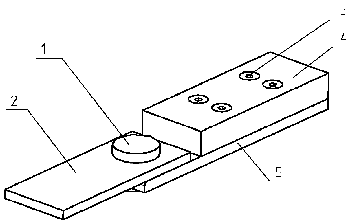
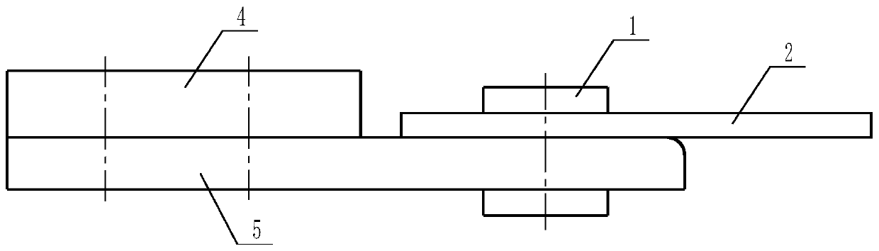
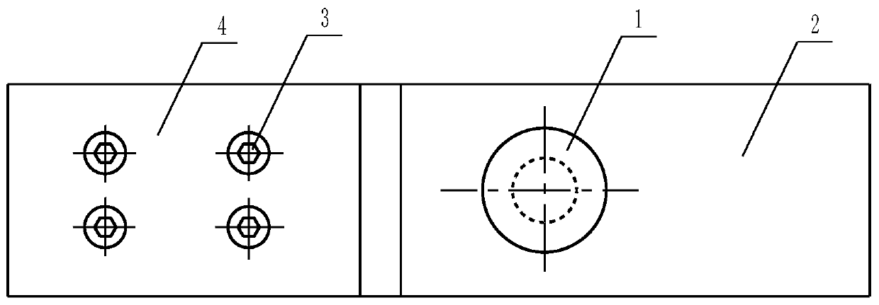
[0058] An anti-bending fixture for a single-lap riveted joint, the innovation of which is that it includes an upper splint 4, a lower splint 5, and a single-lap joint test piece 2, and the lower splint 5 includes a first splint section at the fixed end and a second splint section at the riveted end , the corresponding positions of the single lap joint test piece and the second splint section of the lower splint are provided with rivet mounting holes 6, and the rivets 1 pass through the rivet mounting holes to rivet and fix the single lap joint test piece and the second splint section of the riveted end of the lower splint, The upper splint and the first splint section of the lower splint are fixed by countersunk screws 3, the length of the fi...


PUM


Abstract

The invention relates to a single lap riveted joint anti-bend fixture which is characterized by comprising an upper clamping plate, a lower clamping plate and a single lap joint test piece, wherein the lower clamping plate comprises a first clamping plate section at a fixing end and a second clamping plate section at a riveting end; the single lap joint test piece is fixedly riveted with the second clamping plate section of the lower clamping plate by virtue of rivets; the upper clamping plate and the first clamping plate section of the lower clamping plate are fixed by a countersunk screw. The invention further relates to a design method of the single lap riveted joint anti-bend fixture. The design method comprises the following steps: 1) determining a thickness of the single lap joint test piece and a diameter of a rivet mounting hole according to test requirements; 2) calculating to analyze the maximum turning angle and maximum deflection at the single lap riveted joint; 3) optimizing and determining the thickness of the upper clamping plate. The single lap riveted joint anti-bend fixture disclosed by the invention is scientific and reasonable in structural design and convenientto clamp, excessive bending deformation of the single lap riveted joint can be effectively avoided, and the influence of bending on fatigue test results are avoided.

Description

technical field [0001] The invention belongs to the technical field of fatigue experiments and relates to a single-lap riveted joint anti-bending fixture and a design method thereof. Background technique [0002] The single-lap riveting connection method is widely used in various mechanical connection components, especially in the aircraft skin riveting structure. These connection parts are dangerous parts of aircraft structure fatigue and need to be verified by fatigue tests. In practical applications, most of the single-lap riveted joints are large-area multi-rivet plates, and the bending of the riveted joints is alleviated. However, since the two joints of single lap riveting are not on the same plane after all, and the length of the experimental specimen is limited, the force of the two joints in the riveting fatigue test is obviously not on the same plane, resulting in bending deformation of the single lap riveting joint If the length of the test piece is too short, it...

Claims


Application Information

Patent Timeline
Patent Type & Authority Patents(China)
IPC IPC(8): G01N3/04G01M13/00
CPCG01M13/00G01N3/04G01N2203/04
Inventor 平学成程里朋刘炎捷
Owner TIANJIN UNIV OF SCI & TECH
Why Eureka
Try Eureka