U-shaped device for clamping formwork
A U-shaped and formwork technology, which is applied to the joints of formwork/formwork/work frame, the preparation of building components on site, construction, etc., can solve the problem that the formwork is prone to deformation, unevenness, and the outer surface of the ring beam is not vertical, etc. problems, to achieve the effect of improving the overall rigidity and improving installation efficiency
- Summary
- Abstract
- Description
- Claims
- Application Information
AI Technical Summary
Problems solved by technology
Method used
Image


Examples
Embodiment 1
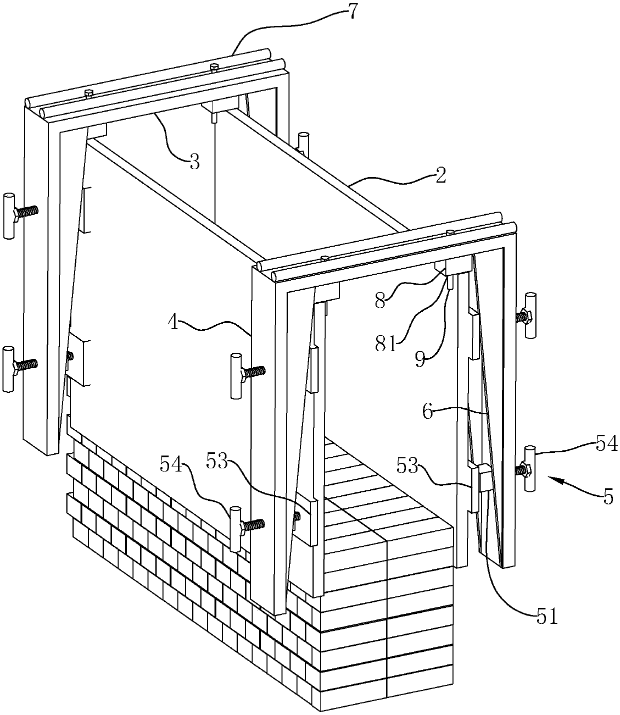
[0036] Such as figure 2 As shown, a U-shaped device for clamping templates includes a horizontal steel plate 3 , two vertical steel plates 4 and at least two pairs of abutting devices 5 . Both ends of the transverse steel plate 3 are fixedly connected to one end of two vertical steel plates 4 respectively, thereby forming a U-shaped piece. The transverse steel plate 3 and the two vertical steel plates 4 of the U-shaped piece are preferentially integrally formed, and may also be connected by welding. Each pair of abutting devices 5 is respectively connected to two vertical steel plates 4 , and different pairs of abutting devices 5 are vertically arranged on the vertical steel plates 4 . The abutment device 5 includes a fixing block 51 and a bolt 52 . The fixed block 51 is welded on the inner surface of the vertical steel plate 4, and the inside of the fixed block 51 is provided with a bolt through hole, and the bolt 52 passes through the bolt through hole toward the ring bea...
Embodiment 2
[0040] Such as image 3 and Figure 4 As shown, the difference from the first embodiment is that: in order to increase the contact area between the abutment device 5 and the ring beam formwork 2 , the ring beam formwork 2 is not damaged by the ends of the bolts 52 . The abutment device 5 further includes an abutment block 53 , which is connected to one end of the bolt 52 close to the ring beam formwork 2 , and the abutment block 53 is in contact with the ring beam formwork 2 .
[0041] After the ring beam concrete pouring is completed, the concrete exerts a pressing force on the ring beam formwork 2, so there is also a great pressure between the ring beam formwork 2 and the abutment block 53. At this time, if you want to loosen the bolt 52, you must overcome The frictional force between the abutment block 53 and the ring beam template 2 makes it difficult to remove the U-shaped device. So, if Figure 5 As shown, one end of the bolt 52 connected to the abutting block 53 is r...
Embodiment 3
[0050] The difference from the first embodiment is that the horizontal steel plate 3 is replaced by a horizontal square steel pipe, and the two vertical steel plates 4 are replaced by two vertical square steel pipes. The square steel pipe has better rigidity than the steel plate, and is not easy to produce bending deformation, so that the U-shaped device has better rigidity without adding additional back ribs 7 and reinforcing plates 6 .
PUM
 Abstract
Description
Claims
Application Information
 - Generate Ideas
- Intellectual Property
- Life Sciences
- Materials
- Tech Scout
- Unparalleled Data Quality
- Higher Quality Content
- 60% Fewer Hallucinations
Browse by: Latest US Patents, China's latest patents, Technical Efficacy Thesaurus, Application Domain, Technology Topic, Popular Technical Reports.
© 2025 PatSnap. All rights reserved.Legal|Privacy policy|Modern Slavery Act Transparency Statement|Sitemap|About US| Contact US: help@patsnap.com