Method and apparatus for manufacturing press component
一种制造方法、制造装置的技术,应用在压制零部件的制造和制造装置领域,能够解决加厚、制造成本上升、弯曲零部件重量增加等问题
- Summary
- Abstract
- Description
- Claims
- Application Information
AI Technical Summary
Problems solved by technology
Method used
Image
Examples
Embodiment 1
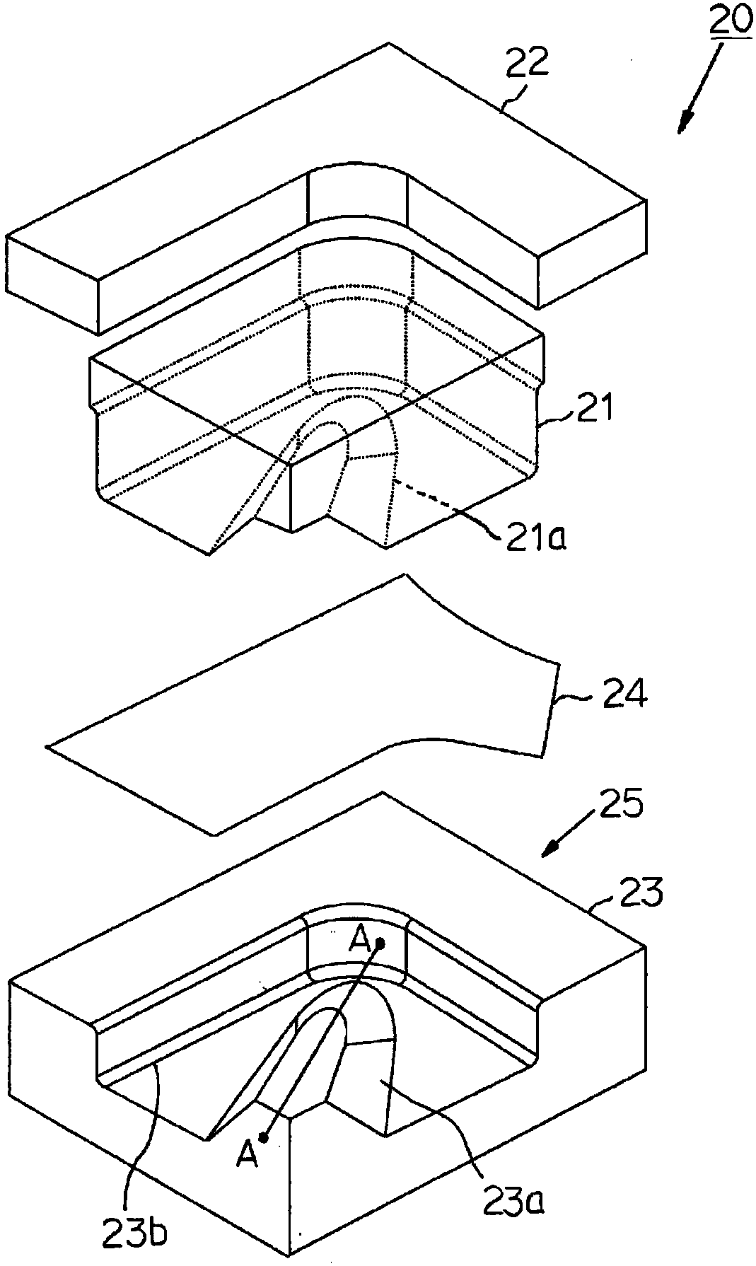
[0216] By using computer-based finite element method for the use of figure 1 Manufacturing device 20 shown in the manufacturing figure 2 Shown intermediate parts 11-1 (example of the present invention), and use Figure 20 For the pressed part (comparative example) manufactured by the manufacturing device 14 shown, the maximum plate thickness reduction rate at the intersection point a of the concave ridge line 11d and the flange 11e at the circumferential center position of the bent portion 13 was analyzed. .
[0217] The specifications of the analyzed intermediate parts 11-1 and pressed parts are as listed below.
[0218] ·The tensile strength of blanks 24 and 18: above 1180MPa, plate thickness: 1.6mm
[0219] ・Height of intermediate parts 11-1 and pressed parts (projection distance of vertical wall 11c in the product height direction): 60mm
[0220] ・Curvature R of the concave ridge line 11d of the intermediate part 11-1 and the pressed part 1 : 20mm when viewed sidewa...
Embodiment 2
[0226] By using computer-based finite element method for the use of figure 1 Manufacturing device 20 shown in the manufacturing figure 2 Shown intermediate parts 11-1 (example of the present invention), and use Figure 20 For the pressed parts manufactured by the manufacturing apparatus 14 shown (comparative example), the maximum plate thickness reduction rate at the intersection point a of the concave ridge line 11d and the flange 11e at the circumferential center position of the bent portion 13 was analyzed.
[0227] Table 1 summarizes the specifications and results of the analyzed intermediate parts 11-1 and pressed parts.
[0228] [Table 1]
[0229]
[0230] In this analysis, the dynamic explicit algorithm using the finite element method was used to calculate, and in the billet 24 with a tensile strength of 980 MPa, it was judged that the maximum plate thickness reduction rate: 15% or more was not at the above-mentioned intersection point a. For cracks, in the bill...
Embodiment 3
[0233] By using computer-based finite element method for the use of figure 1 Manufacturing device 20 shown in the manufacturing Figure 12 The intermediate part 30 (example of the invention) of the T-shaped part shown, and Figure 13 In the intermediate part 31 of the Y-shaped part shown, the maximum plate thickness reduction rate at the intersection point a of the concave ridge line and the flange at the circumferential center position of the bent part was analyzed.
[0234] Table 2 summarizes the specifications and results of the analyzed intermediate components 30 and 31 . In addition, the opening angles in Table 2 refer to Figure 12 , 13 The angle θ in .
[0235] [Table 2]
[0236]
[0237] In this analysis, calculation was performed using a dynamic explicit algorithm using the finite element method, and in the case of a material strength of 1180 MPa, it was judged that there was no crack at the intersection point when the maximum plate thickness reduction rate w...
PUM
 Abstract
Description
Claims
Application Information
 - R&D
- Intellectual Property
- Life Sciences
- Materials
- Tech Scout
- Unparalleled Data Quality
- Higher Quality Content
- 60% Fewer Hallucinations
Browse by: Latest US Patents, China's latest patents, Technical Efficacy Thesaurus, Application Domain, Technology Topic, Popular Technical Reports.
© 2025 PatSnap. All rights reserved.Legal|Privacy policy|Modern Slavery Act Transparency Statement|Sitemap|About US| Contact US: help@patsnap.com


