Efficient building wall surface punching equipment

A technology for drilling equipment and construction, applied in drilling equipment and methods, construction, drilling equipment, etc., can solve the problems of drilling crooked, environmental pollution, increasing labor and economic costs, etc., to facilitate sliding and handling, and improve work Efficiency, the effect of preventing environmental pollution

Inactive Publication Date: 2018-03-27
广州猎狗信息咨询有限公司
View PDF0 Cites 0 Cited by
  • Summary
  • Abstract
  • Description
  • Claims
  • Application Information

AI Technical Summary

Problems solved by technology

[0002] At present, most of the buildings in our country are reinforced concrete walls. While people are increasingly pursuing high-quality life, they also have huge requirements for people's living. Not only do they require complete functions, but they also propose changes in aesthetics. To meet the aesthetics of the building, the wall surface will be decorated and transformed. During the transformation process, especially when the wall is perforated, a large amount of dust will be generated. This dust not only pollutes the environment on the construction site, but also due to the The size is extremely small, and the construction workers will inhale the dust into the body, which will increase the occupational diseases of the construction workers, increase labor and economic costs, and the traditional wall drilling mainly relies on the workers to hold the punching machine to carry out manual drilling. It is conducive to convenient and fast drilling operation, but the problem is that in the process of manual drilling, because only manual experience is used to align the drill bit with the wall, people's hands are prone to shaking when drilling. As a result, it is easy to make the hole crooked, which greatly affects the quality of the hole and the speed of the hole

Method used


Image

  • Efficient building wall surface punching equipment
  • Efficient building wall surface punching equipment
  • Efficient building wall surface punching equipment

Examples


Embodiment Construction

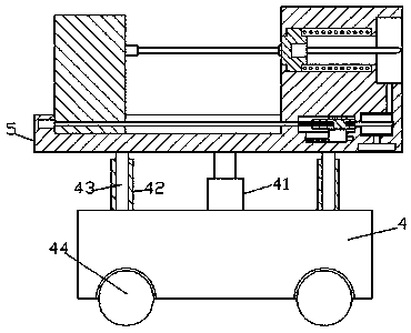
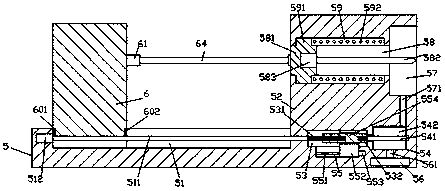
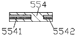
[0022] Such as Figure 1-Figure 5 As shown, a kind of high-efficiency building wall punching equipment of the present invention includes a walking structure 4 and a punching drive structure 5 installed above the walking structure 4, and the top end surface of the left side of the punching drive structure 5 is provided with There is a first sliding groove 51, and the top end surface of the right side of the punching drive structure 5 is fixed with a punching support member 52, and a first threaded rod 511 is extended left and right in the first sliding groove 51, and the first threaded rod 511 The rod 511 is threadedly connected with a sliding block 6 whose top protrudes outside the top end surface of the first sliding groove 51, and the punching drive structure 5 on the right side of the first sliding groove 51 is provided with a first cavity 53 , the said punching driving structure 5 on the right side of the first cavity 53 is provided with a second cavity 54, the bottom of t...


PUM


Abstract

The invention discloses a high-efficiency punching device for building walls, which includes a walking structure and a punching driving structure installed above the walking structure. The top end surface on the right side is fixed with a perforated support member, and the first threaded rod is extended left and right in the first sliding groove. A first cavity is provided in the punching drive structure on the right side of the first cavity, a second cavity is provided in the punching drive structure on the right side of the first cavity, and a second slide slot is provided at the bottom of the first cavity. The second threaded rod extending from the left and right of the second sliding groove is threaded and connected with a guide sliding block whose top extends into the first cavity; the invention has simple structure, convenient operation, and can realize automatic deep drilling and suction Dust collection work, improve work efficiency and prevent environmental pollution caused by dust.

Description

technical field [0001] The invention relates to the technical field of building construction equipment, in particular to an efficient building wall punching equipment. Background technique [0002] At present, most of the buildings in our country are reinforced concrete walls. While people are increasingly pursuing high-quality life, they also have huge requirements for people's living. Not only do they require complete functions, but they also propose changes in aesthetics. To meet the aesthetics of the building, the wall surface will be decorated and transformed. During the transformation process, especially when the wall is perforated, a large amount of dust will be generated. This dust not only pollutes the environment on the construction site, but also due to the The size is extremely small, and the construction workers will inhale the dust into the body, which will increase the occupational diseases of the construction workers, increase labor and economic costs, and th...

Claims


Application Information

Patent Timeline
Patent Type & Authority Applications(China)
IPC IPC(8): E21B7/02E21B15/00E21B19/08E21B19/081E21B21/015
CPCE21B7/02E21B15/00E21B19/08E21B19/081E21B21/015
Inventor 余敏
Owner 广州猎狗信息咨询有限公司
Why Eureka
Try Eureka