
Water-saving new energy irrigation vehicle for municipal garden

A water-saving and new energy technology, applied in the field of municipal gardens, can solve the problems of uneven concentration of solutions, large investment in equipment, and the lack of mixing function of spray tank trucks, so as to facilitate mobile handling, reduce floor space, and facilitate The effect of sprinkler work

Inactive Publication Date: 2018-03-27
成都旭日众鑫科技有限公司
View PDF6 Cites 0 Cited by
  • Summary
  • Abstract
  • Description
  • Claims
  • Application Information

AI Technical Summary

Problems solved by technology

The original extensive irrigation has long been unable to meet modern needs, and refined management has become the development direction. Among them, drip irrigation is especially water-saving, but its equipment investment is large and costly, while sprinkler irrigation is relatively low in cost and water-saving. It is driven by engine oil, which is not very environmentally friendly. The sprinkler racks on the sprinkler irrigation device are generally fixed as a whole, and cannot be unfolded or folded, and the spray tank truck does not have the function of mixing well. Generally, the sprinkler solution is manually mixed. When it is necessary to add chemicals to the water, automatic mixing cannot be realized, resulting in uneven concentration of the solution

Method used


Image

  • Water-saving new energy irrigation vehicle for municipal garden
  • Water-saving new energy irrigation vehicle for municipal garden
  • Water-saving new energy irrigation vehicle for municipal garden

Examples


Embodiment Construction

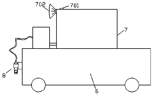
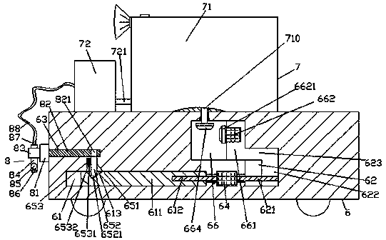
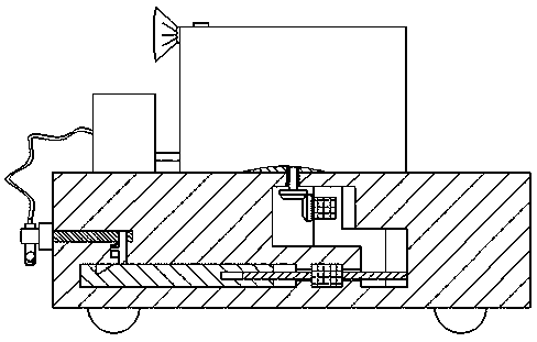
[0021] Such as Figure 1-Figure 6 As shown, a water-saving municipal garden new energy sprinkler vehicle of the present invention includes a sprinkler base 6 and a water storage sprinkler device 7 arranged on the top of the sprinkler base 6 and installed on the left side of the sprinkler base 6 The sprinkler rack device 8 on the side, the water storage sprinkler device 7 is composed of a water storage tank 71 and a sprinkler irrigation pump 72, the water storage tank 71 is connected with a downwardly extending mixing shaft 710, and the water storage tank 71 below The first sliding connection cavity 66 is arranged in the said sprinkling irrigation base 6, and the tail tip of the bottom of the mixing shaft 710 penetrates into the first sliding connection cavity 66 and the tail tip is fixedly provided with a first cone runner 664. A first sliding joint block 661 is slidably connected to the first sliding joint cavity 66 on the right side of the first cone runner 664, and a first ...


PUM


Abstract

The invention discloses a water-saving new energy irrigation vehicle for a municipal garden. The vehicle comprises a spray irrigation base, a water storage spray irrigation device arranged on the topof the spray irrigation base and a spray irrigation rack device installed on the left side face of the spray irrigation base. The water storage spray irrigation device consists of a water storage tankand a spray irrigation pump, a mixing shaft extending downwards is in transfer connection with the inside of the water storage tank, a first slid joint chamber is formed in the spray irrigation basebelow the water storage tank, the tail sheath of the bottom portion of the mixing shaft touches the inside of the first slide joint chamber, a first cone runner is fixedly arranged on the tail sheathof the bottom portion of the mixing shaft, and a first slide joint block is slidably connected with the inside of the first slide joint chamber on the right side of the first cone runner; a first driving device is arranged in the left side face of the upper side of the first slide joint block, and the left side of the first driving device is cooperatively connected with a second cone runner that touches the outside of the life side face of the first slide joint block and is cooperatively connected with the first cone runner; and a second driving device is arranged in the spray irrigation basebelow the first slide joint chamber. The vehicle is simple in structure, convenient in operation, disassembly, installation, move, transportation and maintenance work and has the advantages that the time and labor are saved, the mixing is even, and the work efficiency is improved.

Description

technical field [0001] The invention relates to the technical field of municipal gardens, and relates to a water-saving new energy sprinkler irrigation vehicle for municipal gardens. Background technique [0002] Water resources are precious, especially in water-scarce areas where there is not enough rain. In these places, agricultural irrigation needs to be carried out in strict compliance with the principle of water conservation to avoid damage to the environment. The original extensive irrigation has long been unable to meet modern needs, and refined management has become the development direction. Among them, drip irrigation is especially water-saving, but its equipment investment is large and costly, while sprinkler irrigation is relatively low in cost and water-saving. It is driven by engine oil, which is not very environmentally friendly. The sprinkler racks on the sprinkler irrigation device are generally fixed as a whole, and cannot be unfolded or folded, and the sp...

Claims


Application Information

Patent Timeline
Patent Type & Authority Applications(China)
IPC IPC(8): A01G25/09B01F7/18B05B9/04B05B15/00
CPCA01G25/09B05B9/007B05B9/0403B01F27/90Y02A40/22
Inventor 汪任斌
Owner 成都旭日众鑫科技有限公司
Learn More