Eureka AIR delivers breakthrough ideas for toughest innovation challenges, trusted by R&D personnel around the world.

Multifunctional laminating machine and usage method thereof

A laminator, multi-functional technology, applied in the direction of photovoltaic power generation, sustainable manufacturing/processing, electrical components, etc., can solve the problems that cannot meet the lamination requirements of flexible components and special solar cell components, and achieve the effect of multi-functionality

Pending Publication Date: 2018-03-23
HEBEI YIHENG SCI & TECH CO LTD
View PDF10 Cites 8 Cited by
  • Summary
  • Abstract
  • Description
  • Claims
  • Application Information

AI Technical Summary

Problems solved by technology

[0009] The purpose of the present invention is to provide a multi-functional laminator and its use method, which can not only encapsulate conventional solar cell components, but also meet the lamination requirements of special solar cell components such as flexible components and double-glass components, and solve the existing problems. The problem that the laminator cannot meet the lamination requirements of special solar cell components such as flexible components and double-glass components

Method used

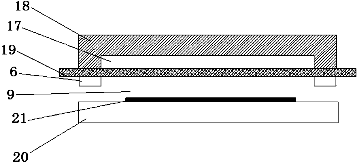
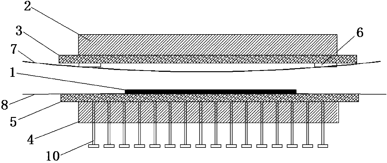
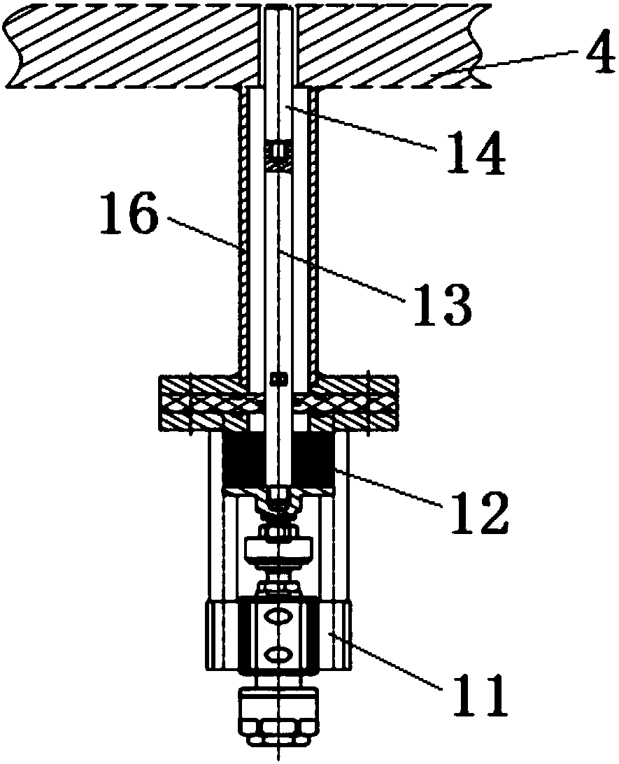

Image

  • Multifunctional laminating machine and usage method thereof
  • Multifunctional laminating machine and usage method thereof
  • Multifunctional laminating machine and usage method thereof

Examples


Embodiment Construction

[0048] The present invention will be further described below in combination with specific embodiments and corresponding drawings.

[0049] It should be understood that the appended drawings are not to scale, presenting a suitably simplified representation of various features illustrative of the basic principles of the invention. The specific design features of the invention disclosed herein, including, for example, specific dimensions, orientations, locations and shapes will be determined in part by the particular intended application and use environment.

[0050] In the accompanying figures, the same or equivalent parts (elements) are designated with the same reference numerals.

[0051] Such as figure 2 As shown, the multifunctional laminator described in the embodiment of the present invention includes an upper chamber working mechanism and a lower chamber working mechanism located below the upper chamber working mechanism, and the upper chamber working mechanism passes t...


PUM


Abstract

The invention relates to a multifunctional laminating machine and a usage method thereof. The multifunctional laminating machine comprises an upper chamber working mechanism and a lower chamber working mechanism. The upper chamber working mechanism comprises an upper chamber workbench and an upper chamber rubber plate which are used for heating or cooling assembly products. The periphery of the upper chamber rubber plate is hermetically connected with the periphery of the lower surface of the upper chamber workbench. The lower chamber working mechanism comprises a lower chamber workbench and alower chamber rubber plate which are used for heating or cooling assembly products. The periphery of the lower chamber rubber plate is hermetically connected with the periphery of the upper surface of the lower chamber workbench. The upper workbench and the lower bench realize the heating or cooling functions according to different assembly products. Meanwhile, the lamination of assembly productscan be realized based on different working states of the upper rubber plate and the lower rubber plate. According to the invention, conventional solar cell modules can be packaged, and the laminationrequirements of flexible assemblies, double-glass assemblies and other special solar cell modules can also be met. The invention can also be used for packaging other types of assembly products, so that the multi-functionality of one laminating machine is realized.

Description

technical field [0001] The invention belongs to the technical field of encapsulation, and in particular relates to a multifunctional laminator and a method for using the same, which can be applied to the encapsulation of solar cell components, and can also be used for other component products requiring lamination encapsulation. Background technique [0002] With the process of global industrialization, human demand for energy is constantly increasing. As an inexhaustible green energy source, solar energy has received great attention in various researches on utilizing solar energy. Among them, the development of solar cell technology is particularly rapid. At present, various types of solar cell components have appeared on the market, including special components such as flexible components and double-glass components in addition to conventional components. [0003] Encapsulation is a key step in the production of solar cell components. A good battery encapsulation can not o...

Claims


Application Information

Patent Timeline
Patent Type & Authority Applications(China)
IPC IPC(8): H01L31/18H01L31/048
CPCH01L31/048H01L31/18Y02E10/50Y02P70/50
Inventor 刘馨禧崔凯徐伟吴学耕刘艳婷肖慧婷包智鑫章学峰李若鹏齐利江
Owner HEBEI YIHENG SCI & TECH CO LTD
Why Eureka
Eureka Blog
Learn More