
Sintering ignition furnace and ignition control process thereof

A technology of ignition control and sintering point, which is applied in the direction of furnace, burner, furnace type, etc., can solve the problems of poor ignition effect and easy over-melting of material surface, etc., and achieve the effect of ensuring ignition intensity and enhancing side ignition intensity

Pending Publication Date: 2018-03-23
MAANSHAN IRON AND STEEL COMPANY
View PDF1 Cites 2 Cited by
  • Summary
  • Abstract
  • Description
  • Claims
  • Application Information

AI Technical Summary

Problems solved by technology

[0005] Aiming at the problem that the ignition furnace in the prior art is easy to over-melt in the middle of the material surface and the ignition effect on both sides is poor, the present invention provides a sintering ignition furnace and its ignition control process

Method used


Image

  • Sintering ignition furnace and ignition control process thereof

Examples


Embodiment 1

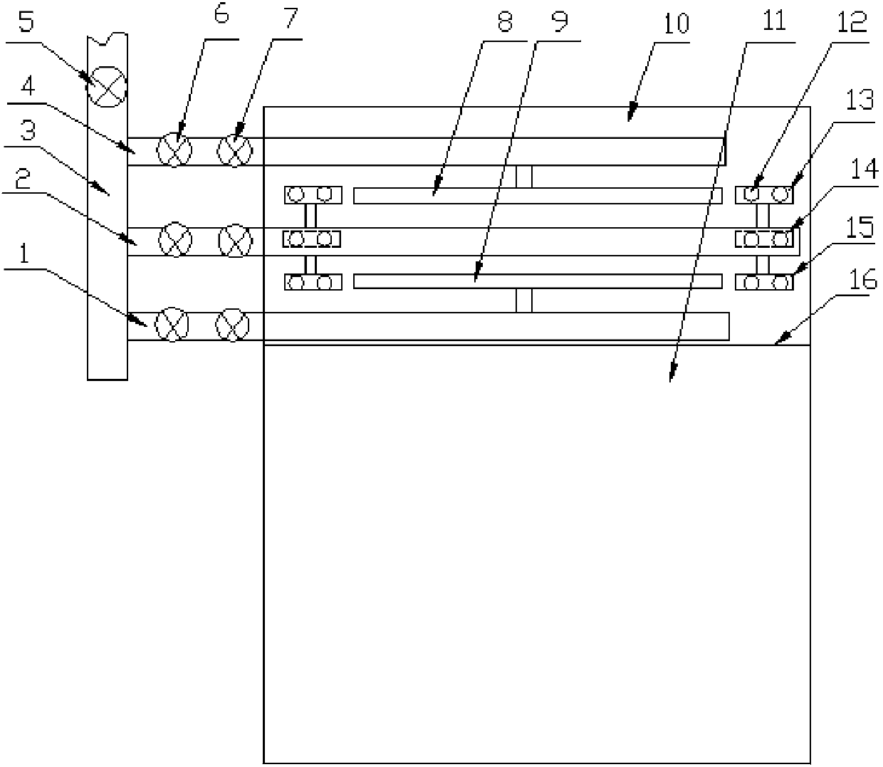
[0031] A sintering ignition furnace includes an ignition chamber 10, and more than one row of side burner gas pipes 2 are added in the ignition chamber 10, and several rows of side burner gas pipes 2 are provided at both ends of the side burner gas pipes 12. The side burner gas pipe 2 is no longer provided with a burner, relying on the ignition intensity of other gas pipe consoles in the middle of the car, and several groups of side burners 12 provided at both ends of the side burner gas pipe 2 are for the two sides of the trolley. Zone ignition to enhance the intensity of side ignition and control the effect of edge ignition on both sides.

Embodiment 2

[0033] A sintering ignition furnace, each row of side burners 12 has one or more pieces, all of which are connected to the side burner gas pipes 2 . The number of side burners 12 in each row can be determined according to the specific working conditions on site. Each row of side burners 12 is arranged along the lateral direction of the edge areas on both sides of the trolley, which can finally ensure the lateral direction of the edge area of ​​the trolley. , to enhance the side ignition intensity and control the edge ignition effect on both sides.

Embodiment 3

[0035] A sintering ignition furnace has one or more rows of side burners 12 in total, all of which are in communication with gas pipes 2 of the side burners. The number of rows of side burners 12 can be determined according to the specific working conditions on site. Each row of side burners 12 is arranged along the longitudinal direction of the edge areas on both sides of the trolley, which can finally ensure the longitudinal direction of the edge areas of the trolley. Enhance the side ignition intensity and control the edge ignition effect on both sides.


PUM


Abstract

The invention provides a sintering ignition furnace and an ignition control process thereof and belongs to the field of sintering ignition devices. The sintering ignition furnace comprises an ignitionchamber, and one or more rows of side edge nozzle gas pipes are additionally arranged in the ignition chamber. A plurality of rows of side edge nozzles are arranged at the two ends of each side edgenozzle gas pipe correspondingly, and each row of side edge nozzles comprises the one or more side edge nozzles which all communicate with the corresponding side edge nozzle gas pipes. According to thesintering ignition furnace and the ignition control process thereof, aiming at the problems that in the prior art, as for an ignition furnace, the middle of a material surface is prone to being super-fused, and the ignition effect on the two sides is poor, the sintering edge ignition intensity can be guaranteed, and a middle area can also be not super-fused under ignition.

Description

technical field [0001] The invention belongs to the field of sintering ignition devices, in particular to a sintering ignition furnace and an ignition control process thereof. Background technique [0002] The sintering ignition furnace belongs to the production process equipment of the main charge of blast furnace ironmaking. The sintering ignition furnace is one of the key equipment for sintering production. It mainly undertakes the ignition function of the material surface after the trolley is placed. Satisfy the effective ignition and ignition gas consumption of the production process. At present, the nozzles (a certain row) of the mainstream design ignition furnace generally share a gas inlet pipe, and there is no difference between individual nozzles. The main problem is that it cannot meet the differential ignition requirements of the material surface. The temperature in the middle area of ​​the material surface of the trolley is high, and the ignition intensity requ...

Claims


Application Information

Patent Timeline
IPC IPC(8): F27B21/08F23D14/48
CPCF23D14/48F27B21/00
Inventor 周江虹刘益勇杨业吴志勇于敬艾文兵张晨
Owner MAANSHAN IRON AND STEEL COMPANY
Learn More