Hydraulic locking rotary joint

A slewing joint, hydraulic technology, applied in fluid pressure actuating devices, medical science, manipulators, etc., can solve the problem that the size and weight are difficult to meet the design indicators, and achieve the effect of convenient control, large slewing torque, and reliable bearing.

Pending Publication Date: 2018-03-20
XIANJU XINGZHI TECH CO LTD
View PDF11 Cites 4 Cited by
  • Summary
  • Abstract
  • Description
  • Claims
  • Application Information

AI Technical Summary

Problems solved by technology

However, with the continuous miniaturization of man-machine collaborative manipulators, master-slave manipulators, medical equipment, and optical instruments, the size and weight of existing locking devices for various rotary joints have been difficult to meet the design specifications

Method used


Image

  • Hydraulic locking rotary joint
  • Hydraulic locking rotary joint
  • Hydraulic locking rotary joint

Examples


Embodiment Construction

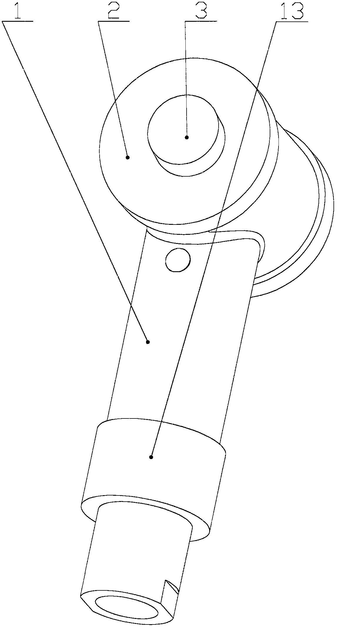
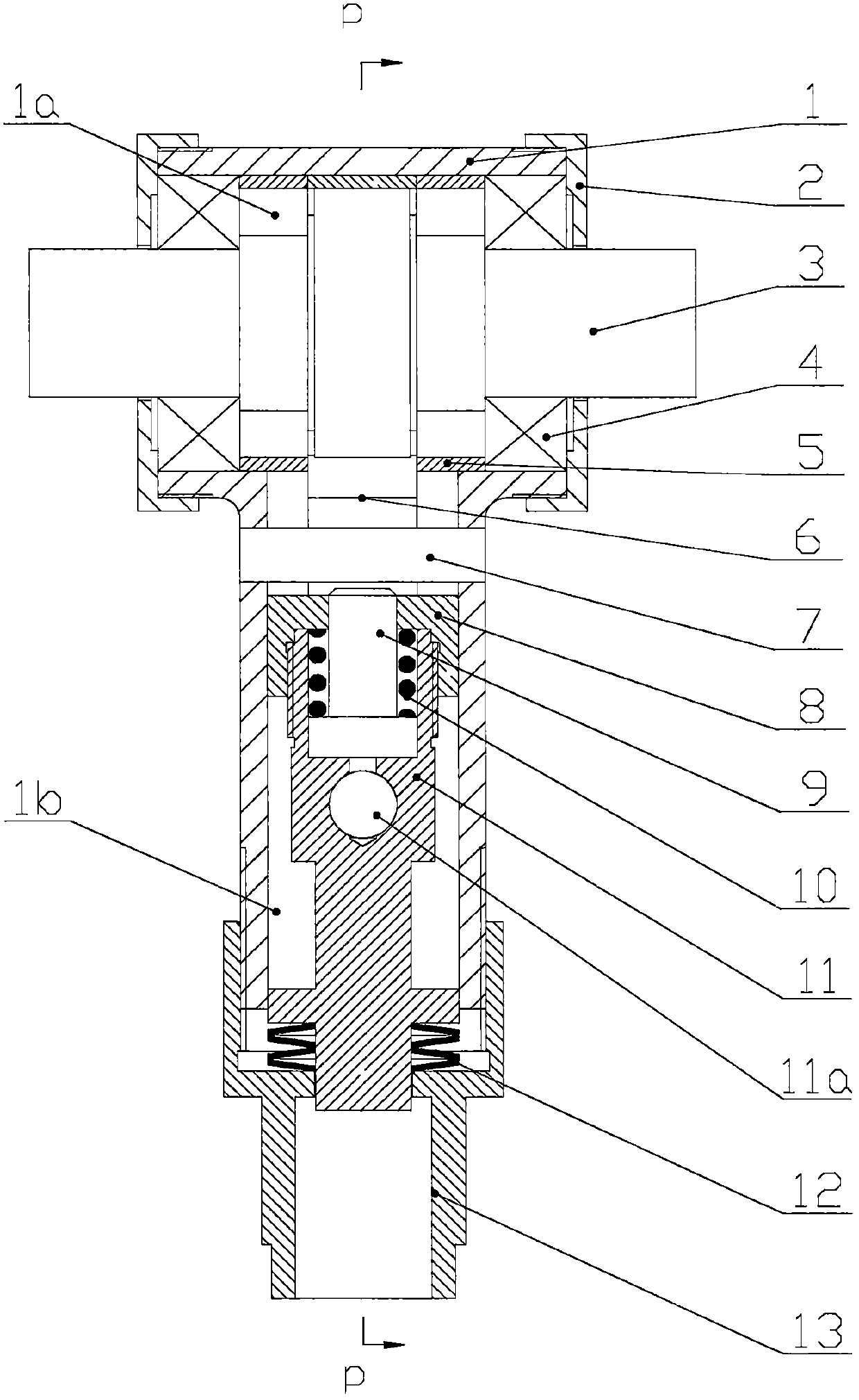
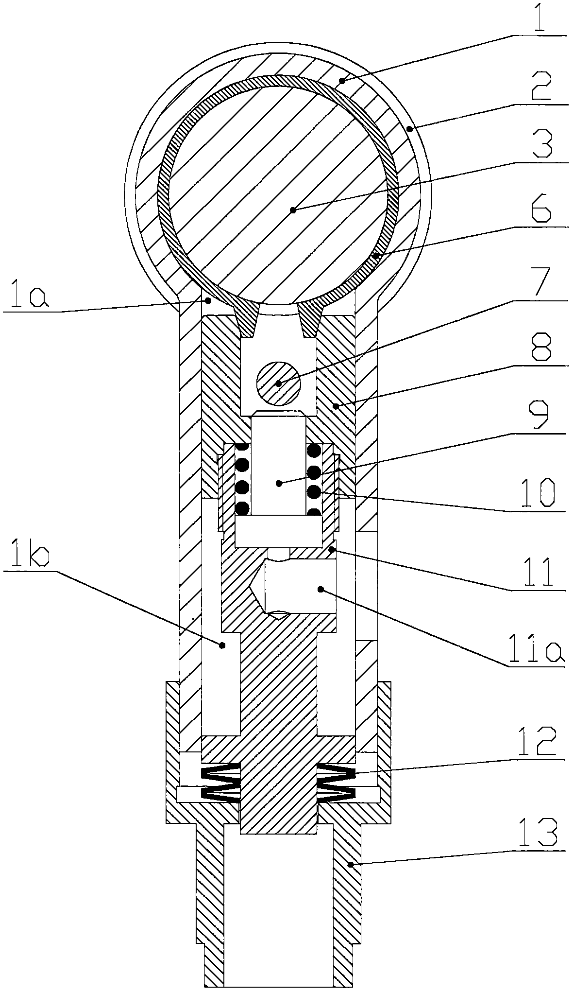
[0019] As shown in the accompanying drawings, the hydraulic locking rotary joint is mainly composed of a housing 1, a mandrel 3, a braking member 6, an oil cylinder barrel 11, an oil cylinder cover 8, a piston rod 9, a return spring 10, and a disc spring group 12. Its specific structure is that there are channel A 1a and channel B 1b in the shell 1, and the two channels intersect and pass through. A mandrel 3 is supported by a bearing 4 in the channel A 1a, and a brake 6 is installed outside the mandrel 3; 1b is close to the front of channel A 1a, and there is a radial stop pin 7 with both ends fixed on the casing 1, and a gland 13 is installed at the rear of channel B 1b; oil cylinder barrel 11 and oil cylinder cover 8 are also installed in channel B 1b , piston rod 9, return spring 10 composed of a hydraulic cylinder, the boss at the front end of the cylinder cover 8 is in contact with the brake piece 6, the front end of the piston rod 9 is in contact with the stop pin 7, and...


PUM


Abstract

The invention relates to a hydraulic locking rotary joint. Two interpenetrating channels are formed in a housing, in one channel, a mandrel is supported by a bearing, a braking piece is installed outside the mandrel, and the mandrel and the housing are relative rotating members of the rotary joint; a miniature hydraulic cylinder is installed in the other channel, and the back part of a cylinder barrel is pressed against a disc spring group. When low-pressure oil is introduced into an oil cylinder, the disc spring group is pressed against the cylinder barrel, so that the braking piece is pressed by the inclined plane of a boss on a cylinder cover on the front end of the cylinder barrel, the mandrel is tightly held, and the rotary joint is in a locking state; when high-pressure oil is introduced into the oil cylinder, a piston rod protrudes to withstand a stop pin, the piston rod stops moving, the cylinder barrel overcomes the thrust of the disc spring group to retract, the inclined plane of the boss on the cylinder cover leaves the braking piece, the mandrel is loosened, and the rotary joint is in a rotatable state. The rotary joint has the advantages of small size, light weight, large locking force, large bearing rotary torque and convenience in control. By adopting the rotary joint, the performance of a rod-shaped serial mechanism, especially an endoscope bracket and the likecan be obviously improved.

Description

technical field [0001] The invention relates to key components of a rod-shaped series mechanism, in particular to a hydraulic locking rotary joint. Background technique [0002] Rod-shaped series mechanisms are widely used in manipulators, multi-degree-of-freedom position adjustment devices, and end-effector displacement mechanisms. When the rotary joint is working, it needs to change the rotation or locking state according to the requirements of the working conditions, that is, it must be equipped with a controllable locking device. At present, there are many types of locking devices, such as the type disclosed in the Chinese patent "200510092591 An Electromagnetic Locking Device for Slewing Joints". However, with the continuous miniaturization of human-machine collaborative manipulators, master-slave manipulators, medical equipment, and optical instruments, the size and weight of existing locking devices for various rotary joints have been difficult to meet the design spe...

Claims


Application Information

Patent Timeline
IPC IPC(8): B25J17/00B25J19/00A61B1/00F15B15/14
CPCA61B1/00149F15B15/1423B25J17/00B25J19/0004
Inventor 马建群
Owner XIANJU XINGZHI TECH CO LTD
Why Eureka
Try Eureka