
Turning center clamp of irregular eccentric valve deck

A turning center, eccentric valve technology, applied in clamping, clamping devices, manufacturing tools, etc., can solve problems such as low efficiency, negative impact on parts machining accuracy, and long processing time for a single piece, achieving low technical level requirements, easy to use Clamping and disassembly to ensure the effect of machining accuracy

Inactive Publication Date: 2018-03-20
JIANGSU UNIV
View PDF9 Cites 4 Cited by
  • Summary
  • Abstract
  • Description
  • Claims
  • Application Information

AI Technical Summary

Problems solved by technology

[0002] At present, due to its irregular structure and unique shape, the processing of the eccentric valve cover is laborious and laborious. Machining centers are generally used for processing. However, the use of machining centers has the following problems: the surface roughness does not meet the requirements, and the processing time for a single piece is long. Efficiency Low, can not meet the requirements of mass production
When the turning center is used to process the valve cover, when the end face is turned, the structure of the part is irregular and eccentric, and the part rotates unbalanced after being installed in the fixture. It is necessary to overcome the impact on the machining accuracy of the part caused by the unbalance of the fixture during processing. Influence and the program of the turning center machining should be adjusted accordingly, otherwise it will also have a certain negative impact on the machining accuracy of the parts, and it will be difficult to effectively guarantee the pass rate of product quality

Method used


Image

  • Turning center clamp of irregular eccentric valve deck
  • Turning center clamp of irregular eccentric valve deck
  • Turning center clamp of irregular eccentric valve deck

Examples


Embodiment Construction

[0026] The present invention will be further described below in conjunction with the accompanying drawings and specific embodiments, but the protection scope of the present invention is not limited thereto.

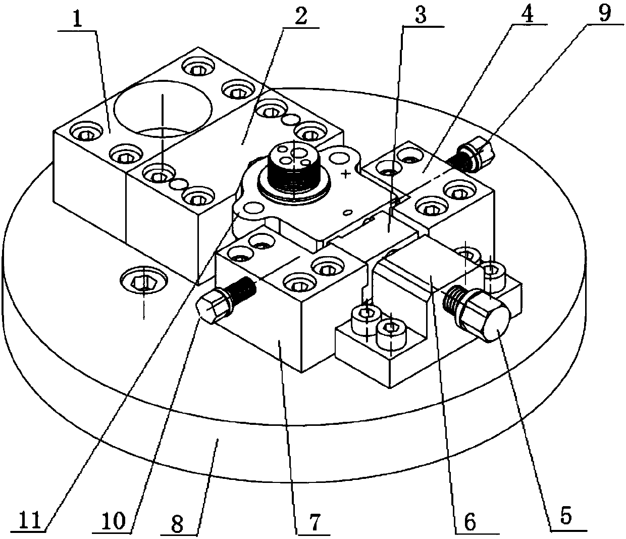
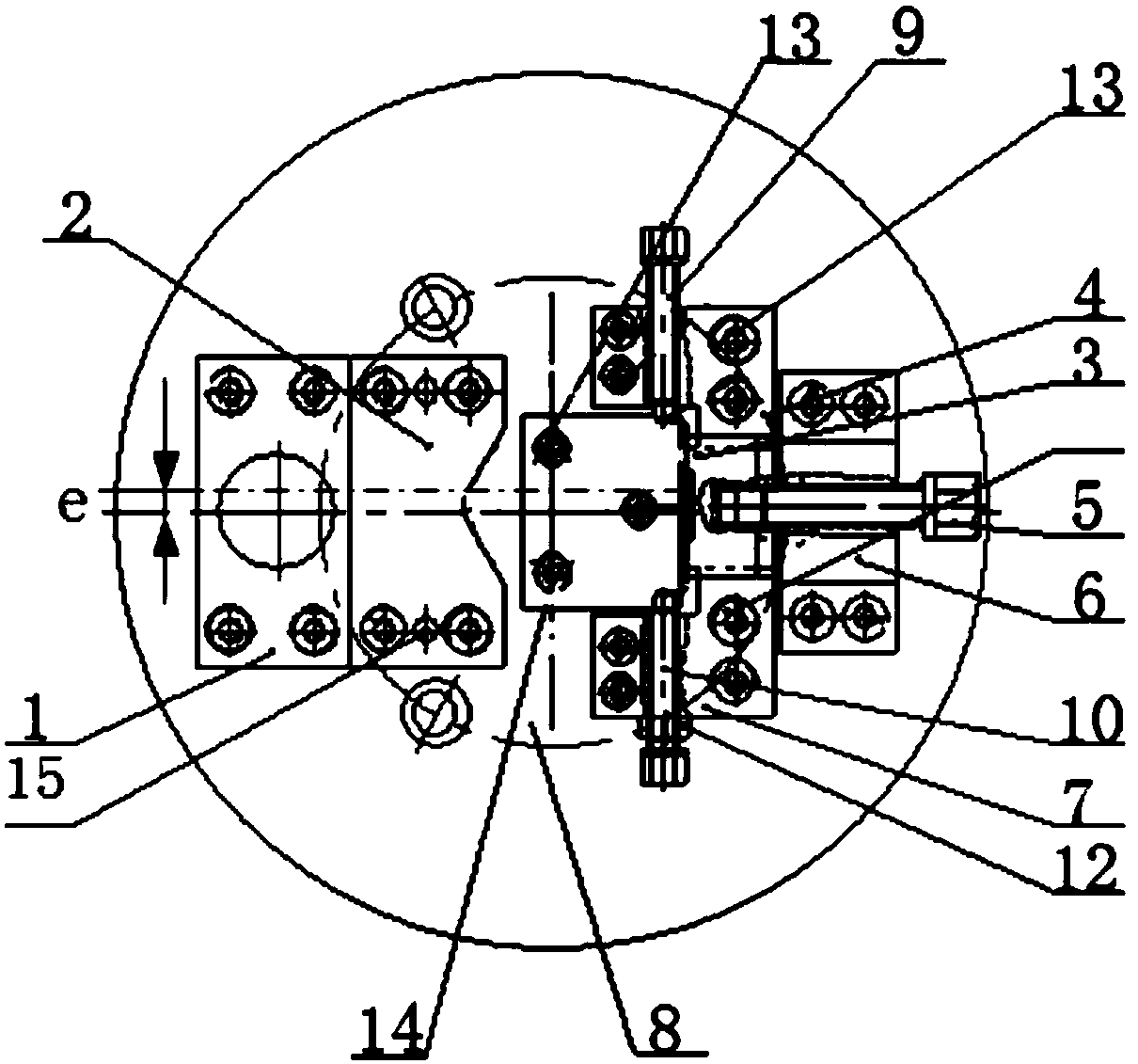
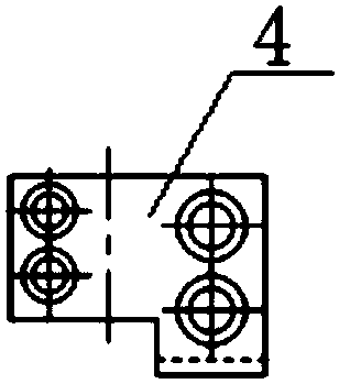
[0027] Such as figure 1 and figure 2 As shown, a turning center fixture for an irregular eccentric bonnet according to the present invention includes a flange 8 and a positioning mechanism installed on the flange 8, a clamping mechanism and a counterweight 1, and the positioning mechanism Including V-shaped positioning block 2, positioning bottom plate 14, upper limit block 4, lower limit block 7, movable screw 9 and first compression screw 10, the clamping mechanism includes movable pressure block 3, second compression screw 5 and Press seat 6. In this embodiment, there is an eccentricity of 1.75 mm between the outer circle to be processed on the valve cover part 11 and the center of the surface of the valve cover part 11 .

[0028] The positioning bottom plate 14 is...


PUM


Abstract

The invention provides a turning center clamp of irregular eccentric valve deck. The turning center clamp comprises a flange plate, a positioning mechanism, a clamping mechanism and a balancing weight. The positioning mechanism, the clamping mechanism and the balancing weight are installed on the flange plate. The positioning mechanism comprises a V-shaped positioning block, a positioning bottom plate, an upper limiting block, a lower limiting block, a movable screw and a first compression screw. The clamping mechanism comprises a movable pressing block, a second compression screw and a pressing base. A space where valve deck parts are placed is formed among the V-shaped positioning block, the upper limiting block, the lower limiting block and the movable pressing block. The valve deck parts are placed on the positioning bottom plate and located in the middle of the flange plate. The movable screw, the first compression screw and the movable pressing block clamp the valve deck parts. The balancing weight is used for balancing the center of mass of all the parts on the flange plate. The turning center clamp is simple in structure, easy to assemble and disassemble, capable of effectively fixing valve deck parts and low in machining cost.

Description

technical field [0001] The invention relates to a turning fixture, in particular to a turning center fixture of an irregular eccentric valve cover. Background technique [0002] At present, due to its irregular structure and unique shape, the processing of the eccentric valve cover is laborious and laborious. Machining centers are generally used for processing. However, the use of machining centers has the following problems: the surface roughness does not meet the requirements, and the processing time for a single piece is long. Efficiency Low, can not meet the requirements of mass production. When the turning center is used to process the valve cover, when the end face is turned, the structure of the part is irregular and eccentric, and the part rotates unbalanced after being installed in the fixture. It is necessary to overcome the impact on the machining accuracy of the part caused by the unbalance of the fixture during processing. Influence and the program of the turni...

Claims


Application Information

Patent Timeline
IPC IPC(8): B23Q3/12
CPCB23Q3/12B23Q2703/10
Inventor 顾佩兰张松生张应龙汪光远何鹏徐晓翔
Owner JIANGSU UNIV
Learn More