
Transformer Oil Cooling System

A technology of cooling system and transformer oil, applied in the direction of transformer/inductor cooling, control/regulation system, non-electric variable control, etc., can solve the problems of coil aging, explosion, transformer damage, etc., and achieve high cooling efficiency and cooling efficiency High and complete cooling effect

Active Publication Date: 2019-03-19
无锡威凯得精密机械有限公司
View PDF2 Cites 0 Cited by
  • Summary
  • Abstract
  • Description
  • Claims
  • Application Information

AI Technical Summary

Problems solved by technology

The existing transformers mainly have the following disadvantages: first, the transformer itself has a large lateral volume, which is inconvenient for transportation and maintenance; second, in order to maintain the rated capacity of the transformer and maintain the service life of itself and the components of the transformer, the The maximum temperature should be kept below 95 degrees, and the temperature exceeds 65 degrees of the external temperature. The failure of the temperature regulation of the transformer may cause the destruction of the transformer, or the service life may be significantly reduced, and the damaged transformer unit may need to be replaced. lead to higher industrial costs
Transformers are often caused by excessive oil temperature, resulting in a decline in the insulation performance of the transformer oil, aging coils, and even accidents such as transformer fires and explosions.

Method used


Image

  • Transformer Oil Cooling System
  • Transformer Oil Cooling System
  • Transformer Oil Cooling System

Examples


Embodiment Construction

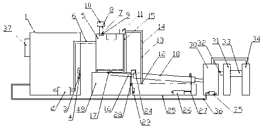
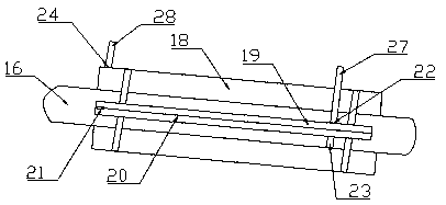
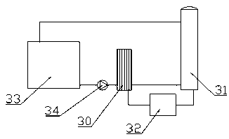
[0023] The present invention will be described in detail below with reference to the drawings, such as Figure 1-5 As shown, a transformer oil cooling system includes an oil-immersed transformer 1, the oil-immersed transformer 1 is fixedly installed on the ground, the oil-immersed transformer 1 is provided with a preliminary cooling mechanism, and the preliminary cooling mechanism consists of Suction pump 1 fixedly installed inside the oil-immersed transformer 1, a temperature sensor 3 fixedly installed on the inner side of the oil-immersed transformer 1, a signal transmitter located inside the temperature sensor 3, and a fixed installation in the oil-immersed transformer 1. The support frame 48 on the ground outside of the type transformer 1, the cylindrical cooling box 5 fixedly installed on the upper surface of the support frame 48, one end is fixedly connected to the outlet of the suction pump 1-2, and the other end extends into the oil outlet pipe above the cylindrical cool...


PUM


Abstract

The invention discloses a transformer-oil cooling system. The transformer-oil cooling system comprises an oil-immersed transformer, the oil-immersed transformer is provided with a primary cooling mechanism, and the primary cooling mechanism is provided with a first suction pump, a temperature inductor, a signal projector, a cylindrical cooling box, an oil outlet pipe, an air outlet, an air outletpipe, an oil-air separator, an air sucking pump, an air blower, a cool air opening, an air inlet pipe, an impurity filter and a multi-way pipe; the oil-immersed transformer is provided with a secondary cooling mechanism, and the secondary cooling mechanism is provided with an oil outlet conduit, an electronic shutoff valve, a cooling water pipe, an inner pipe, a layering piece, a water through opening, a water inlet, a water outlet, a water outlet hole, a water storage tank, a water suction pump, a water inlet pipe, a water outlet pipe and a refrigeration piece; the oil-immersed transformer isprovided with a final cooling mechanism, and the final cooling mechanism is provided with an evaporator, a liquid storage barrel, an expansion valve, a condenser, a refrigeration compressor, a secondsuction pump and an oil inlet pipe; the oil-immersed transformer is externally provided with a controller. The transformer-oil cooling system has the advantages of being simple in structure and highin practicability.

Description

Technical field [0001] The invention relates to the field of heat energy exchange, in particular to a variable pressure oil cooling system. Background technique [0002] Transformer is an important and indispensable power equipment in the transmission grid, and it plays a vital role in regulating the voltage of the grid. Power transformers will produce core loss and winding loss during use. These losses will cause the core and winding temperature to rise. In order to ensure the safe and reliable operation of the transformer, the winding temperature of the transformer, the temperature of the core and the temperature of the transformer oil need to be limited within a safe range, so the transformer needs to be cooled. [0003] At present, most of the transformers running on the power grid are still oil-immersed transformers, and more than 80% of them are cooled by natural oil circulation. Existing transformers mainly have the following shortcomings: First, the transformer itself is ...

Claims


Application Information

Patent Timeline
Patent Type & Authority Patents(China)
IPC IPC(8): H01F27/14H01F27/18G05D23/20
CPCG05D23/20H01F27/14H01F27/18
Inventor 许勇莫春明
Owner 无锡威凯得精密机械有限公司
Learn More