


Quick Research
Generate reliable direction feasibility study reports for your R&D in just a few steps.

Technical Q&A
Discover and master advanced knowledge NOW. Basics, ideas, possibilities, all at once.

Find Solutions
As an expert in R&D theories, this can generate solutions to your technical problems instantly.

Evaluate Feasibility
Analyze your overall solution with one click, know your potential R&D risks in advance.

Monitor Landscape
Get weekly tech updates, stay abreast of the latest tech innovations and key insights.
Humidity control method in test of humidity-controllable semiconductor gas sensor
A humidity control and gas sensor technology, which is used in humidity control, control input involving air characteristics, and non-electrical variable control, etc., and can solve the problems of long sample gas desorption time and unsuitability for gas testing.
- Summary
- Abstract
- Description
- Claims
- Application Information
AI Technical Summary
Problems solved by technology
Method used
Image

Examples
Embodiment 1
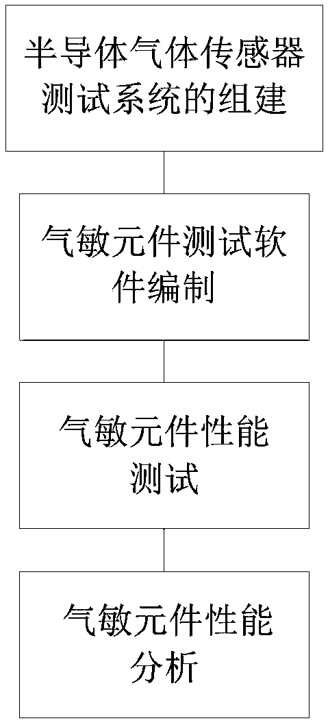
[0068] A test method for a humidity-controllable semiconductor gas sensor, comprising: SnO 2 The steps of preparing gas-sensitive materials, the steps of making gas-sensitive elements, the steps of building and testing the semiconductor gas sensor test system, and the steps of analyzing the performance of the semiconductor gas sensor test system and the semiconductor gas-sensitive element.
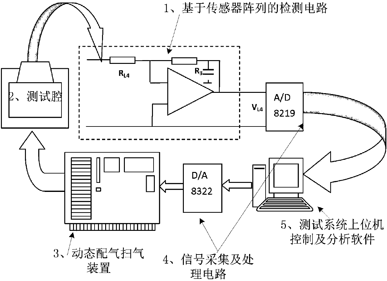
[0069] The step of setting up and testing the gas sensor testing system has a step of controlling the humidity of the air chamber. In this step, a humidity control system is used, including a main controller, a humidity detection sensor, a dehumidifier, an ultrasonic humidifier and The buzzer, wherein the humidity detection sensor, the dehumidifier and the ultrasonic humidifier are installed in the air chamber, and the main controller is respectively connected with the humidity detection sensor, the dehumidifier, the ultrasonic humidifier and the buzzer.
Embodiment 2
[0071] Have the same technical scheme as embodiment 1, more specifically: SnO 2 The steps of gas-sensitive material preparation are: with SnCl 4 ·5H 2 O as raw material, dilute ammonia water as precipitant, weigh a certain amount of SnCl 4 ·5H 2 O raw material, dissolved in an appropriate amount of deionized water, added a small amount of citric acid, stirred to make it completely dissolved, then heated to boiling, and made to react; the prepared dilute ammonia water was slowly added dropwise to the SnCl 4 When the precipitation is complete, wash with warm water and centrifuge for several times to remove the Cl-, then dry the precipitate at 60-100°C, grind it and put it in the muffle furnace Burn at about 700°C for 2 to 4 hours to obtain SnO 2 gas sensitive material.
Embodiment 3
[0073] It has the same technical solution as that of Embodiment 1 or 2, more specifically: in the step of making the gas sensor, the tube core of the sensitive element has a capillary ceramic tube, and the heating wire penetrates into the ceramic tube, The outer coated metal electrode is used as the signal electrode for measuring the resistance of the element, and the gas sensitive material SnO is coated on the outer metal electrode. 2 , and fired;
[0074]The production steps are as follows: the substrate of the ceramic tube coated with metal electrodes at both ends is ultrasonically cleaned with toluene, alcohol and deionized water in sequence, and after drying under the infrared lamp, the ground slurry is coated on the surface of the ceramic tube. and then sintered in a tube-type resistance furnace. Finally, a heating wire with a suitable resistance value is inserted into the burned tube core, and the electrode lead and the heating wire lead are welded on the tube seat of t...
PUM
 Abstract
Description
Claims
Application Information
 - R&D Engineer
- R&D Manager
- IP Professional
- Industry Leading Data Capabilities
- Powerful AI technology
- Patent DNA Extraction
Browse by: Latest US Patents, China's latest patents, Technical Efficacy Thesaurus, Application Domain, Technology Topic, Popular Technical Reports.
© 2024 PatSnap. All rights reserved.Legal|Privacy policy|Modern Slavery Act Transparency Statement|Sitemap|About US| Contact US: help@patsnap.com