Gap adjusting device for main rail and guard rail

A gap adjustment device and technology for gap adjustment, applied to tracks, rails, track superstructures, etc., can solve problems such as derailment of low-floor vehicles, and achieve the effects of avoiding derailment accidents, good stability and safety, and low cost

Active Publication Date: 2018-03-16
ZHUZHOU ELECTRIC LOCOMOTIVE CO
View PDF5 Cites 0 Cited by
  • Summary
  • Abstract
  • Description
  • Claims
  • Application Information

AI Technical Summary

Problems solved by technology

[0004] In order to solve the problem that low-floor vehicles have the risk of derailment when passing standard railway switches, the present invention provides a device for adjusting the gap between main rail and guard rail. The specific technical solution is as follows

Method used


Image

  • Gap adjusting device for main rail and guard rail
  • Gap adjusting device for main rail and guard rail
  • Gap adjusting device for main rail and guard rail

Examples


Embodiment Construction

[0020] The present invention will be described in further detail below in conjunction with the accompanying drawings.

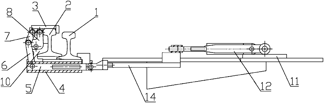
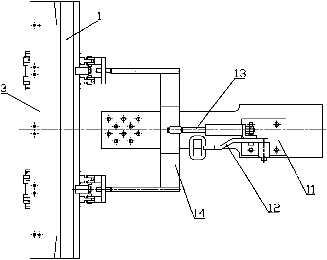
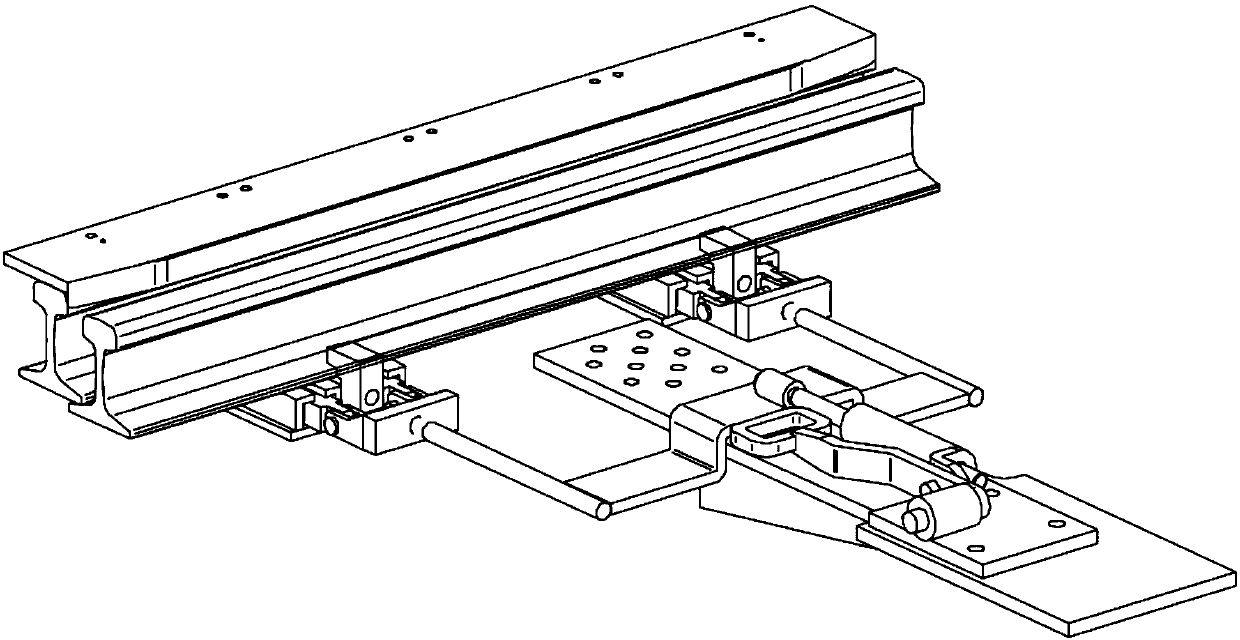
[0021] see Figure 1-7 , a main rail guard rail gap adjustment device, which includes a main rail 1, a guard rail 2 located inside the main rail 1 and a gap adjustment plate 3, and the gap adjustment plate 3 is along the longitudinal direction of the guard rail 2 Extending and having an L-shaped cross-section, the gap adjustment plate 3 is connected to a transmission component, and the transmission component makes the gap adjustment plate 3 in a closed state or an open state. When the gap adjustment plate 3 is in a closed state, the The gap adjustment plate 3 covers the top surface of the guard rail 2 and the side surface of the guard rail 2 opposite to the main rail 1. When the gap adjustment plate 3 is in an open state, the gap adjustment plate 3 is located at the Describe the inside of guard rail 2. It should be noted that the inside is relative to the i...


PUM


Abstract

The invention discloses a gap adjusting device for a main rail and a guard rail. The gap adjusting device comprises the main rail, the guard rail on the inner side of the main rail, and a gap adjusting plate with an L-shaped cross section; the gap adjusting plate can be in a closed or opened state through a transmission component, and when the gap adjusting plate is in the opened state, the gap adjusting plate is located on the inner side of the guard rail, and a rail traffic vehicle with the standard wheel pair inner side distance can normally pass through a railway switch; when the gap adjusting plate is in the closed state, the gap adjusting plate covers the top surface of the guard rail and the side surface, opposite to the main rail, of the guard rail, and the gap between the main rail and the guard rail is reduced so that a rail traffic vehicle with the large wheel pair inner side distance can safely pass through the railway switch. The gap adjusting device is low in cost and construction difficulty, the vehicle producing manufacturing enterprise and the maintenance enterprise can sufficiently use an existing rail device and do not need to redesign or transform the structureof the railway switch, the function is achieved that rail traffic vehicles with different wheel pair inner side distances share the railway switch, and the railway track construction and transformation cost of the enterprise is greatly lowered.

Description

technical field [0001] The invention relates to the technical field of railway tracks, in particular to a main rail guard rail gap adjustment device. Background technique [0002] The low-floor modern tram adopts advanced cutting-edge technology, provides a full-line catenary-free solution, has strong climbing ability, and the minimum turning radius is only 19 meters. The existing roads in the city can be laid with lines. It has large transportation capacity, environmental protection, and low noise. One of the most advanced urban transportation systems in the world today. [0003] The bogies of low-floor vehicles adopt independent wheel sets, and the inner distance of the wheel sets is larger than that of other urban rail vehicles and rolling stock. through its tracks and switches. When the low-floor vehicle runs on the national standard track with a gauge of 1435mm, it can run normally along a straight line, but when the vehicle passes the railway turnout when turning...

Claims


Application Information

Patent Timeline
IPC IPC(8): E01B5/18
CPCE01B5/18E01B2203/012
Inventor 金晓辉周勤孟宪政夏智蒲全卫
Owner ZHUZHOU ELECTRIC LOCOMOTIVE CO
Why Eureka
Try Eureka