Liftable and movable type optical glass cutting device

A technology for optical glass and cutting devices, applied in glass cutting devices, glass manufacturing equipment, manufacturing tools, etc., can solve problems such as uneven cutting surfaces, achieve flat cutting surfaces, ensure stability, and improve work efficiency

Inactive Publication Date: 2018-03-16
CHENGDU KECHUANGGU TECH CO LTD
View PDF0 Cites 7 Cited by
  • Summary
  • Abstract
  • Description
  • Claims
  • Application Information

AI Technical Summary

Problems solved by technology

[0003] The purpose of the present invention is to provide a lifting and moving optical glass cutting device in order to solve the problem that the existing optical glass adopts manual cutting to cause the cutting surface to be uneven.

Method used


Image

  • Liftable and movable type optical glass cutting device
  • Liftable and movable type optical glass cutting device
  • Liftable and movable type optical glass cutting device

Examples


Embodiment 1

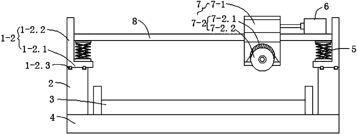
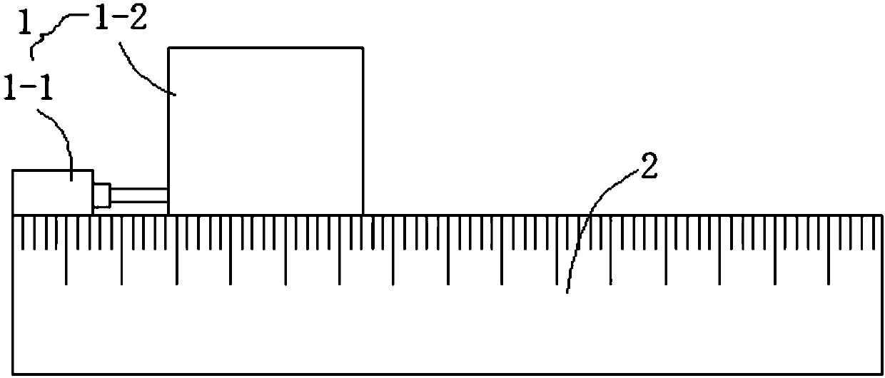
[0022] Such as Figure 1 to Figure 3 As shown, this embodiment provides a lifting and moving optical glass cutting device, including a base 4 and a cutting mechanism 7, the base 4 is provided with a fixed cutting seat 3, and the base 4 is located on both sides of the fixed cutting seat 3. The receiving plate 2 is provided with a moving mechanism 1 with the same structure respectively on the two receiving plates 2. The moving mechanism 1 includes a driving cylinder 1-1 arranged on the top side of the receiving plate 2 and a L fixedly connected with the piston rod of the driving cylinder 1-1. shaped mounting plate 1-2, the bottom of the L-shaped mounting plate 1-2 is provided with a pulley block 1-2.3, and the two receiving plates 2 are respectively provided with guide rails adapted to the pulley block 1-2.3, and the L-shaped mounting plate 1-2 includes a horizontal 1-2.1 and the vertical part 1-2.2, the horizontal part 1-2.1 is provided with a scissor lift mechanism 5, a horizo...

Embodiment 2

[0024] Such as Figure 6 As shown, this embodiment is further optimized on the basis of Embodiment 1, specifically: the scissor lift mechanism 5 includes a scissor bracket 5-1 and a plurality of hydraulic cylinders installed on the scissor bracket 5-1 5-2. The scissors support 5-1 includes a plurality of X-shaped scissors connected end-to-end from top to bottom, two adjacent X-shaped scissors are connected by hinges, and the central points of the X-shaped scissors are connected by a hinge mechanism.

Embodiment 3

[0026] Such as figure 2 As shown, this embodiment is further optimized on the basis of embodiment 1, specifically: the side of the receiving plate 2 away from the fixed cutting seat 3 is evenly distributed with scales along the telescopic direction of the piston rod of the driving cylinder 1-1.


PUM


Abstract

The invention discloses a lifting and moving optical glass cutting device, which relates to the technical field of optical glass processing equipment. The invention includes a base and a cutting mechanism. The base is provided with a fixed cutting seat. There is a moving mechanism with the same structure on the board. The moving mechanism includes a driving cylinder and an L-shaped mounting plate fixedly connected with the driving cylinder. The L-shaped mounting plate includes a horizontal part and a vertical part. The horizontal part is provided with a scissor-type lifting mechanism. A horizontal support plate is connected between the two scissor-type lifting mechanisms, and one end of the horizontal support plate is provided with a telescopic cylinder. The cutting mechanism includes an installation frame and a cutting assembly. It is arranged on the horizontal support plate, and the cutting assembly is arranged on the lower horizontal plate. The invention has simple structure and good stability, and can ensure that the cutting surface of the optical glass obtained by cutting is even.

Description

technical field [0001] The invention relates to the technical field of optical glass processing equipment, and more specifically relates to a lifting and moving optical glass cutting device. Background technique [0002] Optical glass is a glass that can change the direction of light propagation and change the relative spectral distribution of ultraviolet, visible or infrared light. Optical glass in the narrow sense refers to colorless optical glass; optical glass in the broad sense also includes colored optical glass, laser glass, quartz optical glass, anti-radiation glass, ultraviolet and infrared optical glass, fiber optic glass, acousto-optic glass, magneto-optical glass and photochromic Glass. Optical glass requires very high processing precision, otherwise it will affect its light sensing performance. The existing optical glass is usually cut manually, which is inefficient, time-consuming and laborious, and the cutting surface of the optical glass obtained by manual c...

Claims


Application Information

Patent Timeline
Patent Type & Authority Applications(China)
IPC IPC(8): C03B33/023C03B33/03
CPCC03B33/023C03B33/03
Inventor 孙元伟
Owner CHENGDU KECHUANGGU TECH CO LTD
Why Eureka
Try Eureka