Stirring device for slurry mixing tank

A stirring device and slurry mixing tank technology, which is applied in the field of water-based paint production equipment, can solve the problems that materials are easy to adhere to the inner wall and bottom of the tank, and achieve the effects of thorough scraping, convenient disassembly and replacement, and avoiding material waste

Inactive Publication Date: 2018-03-13
TIANJIN DONGDING TECH CO LTD
View PDF0 Cites 2 Cited by
  • Summary
  • Abstract
  • Description
  • Claims
  • Application Information

AI Technical Summary

Problems solved by technology

[0003] In view of this, the purpose of the present invention is to provide a stirring device for a slurry tank to solve the technical problem that the material is easy to adhere to the inner wall and bottom of the tank during the stirring process of the prior art slurry tank

Method used


Image

  • Stirring device for slurry mixing tank
  • Stirring device for slurry mixing tank

Examples


Embodiment Construction

[0018] Specific embodiments of the present invention will be described in detail below in conjunction with the accompanying drawings.

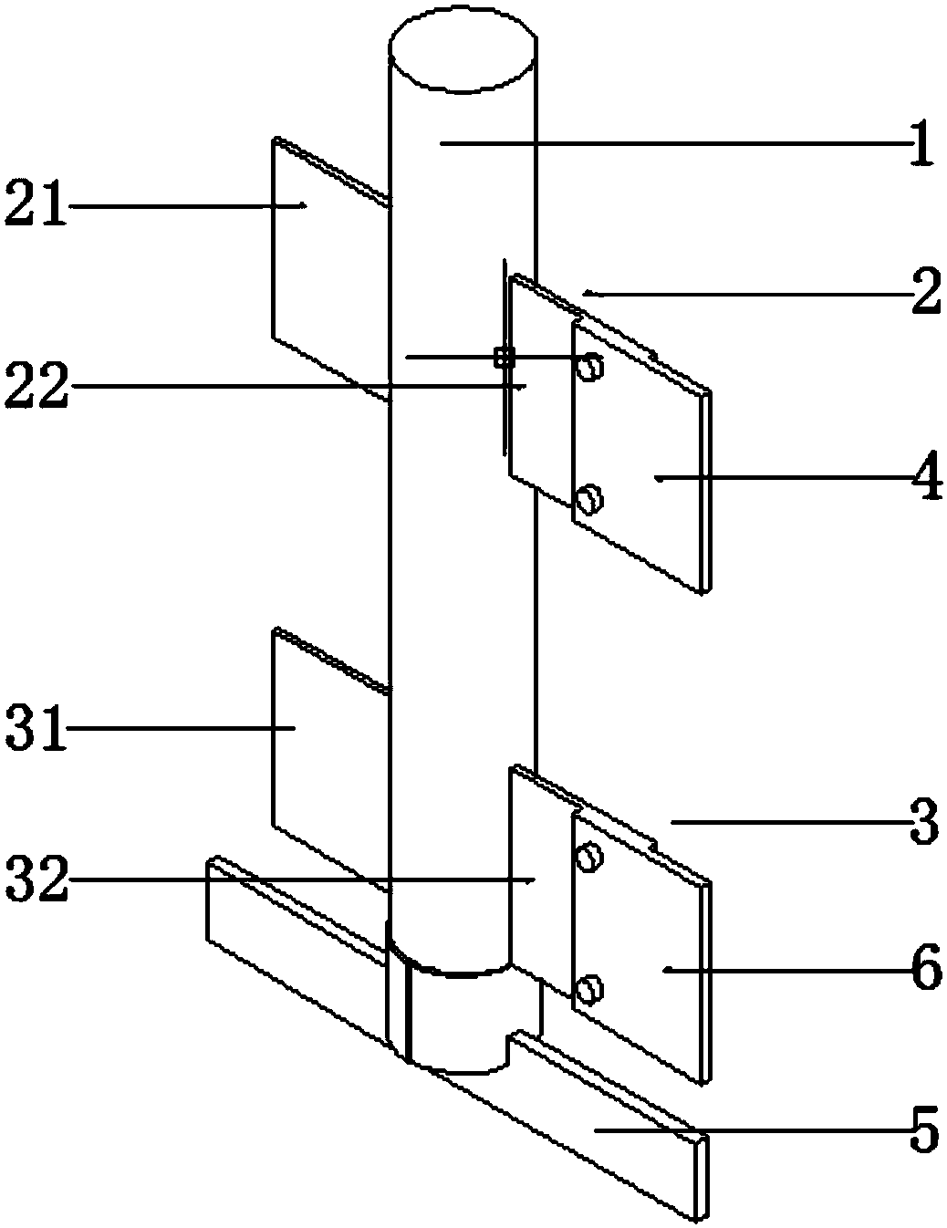
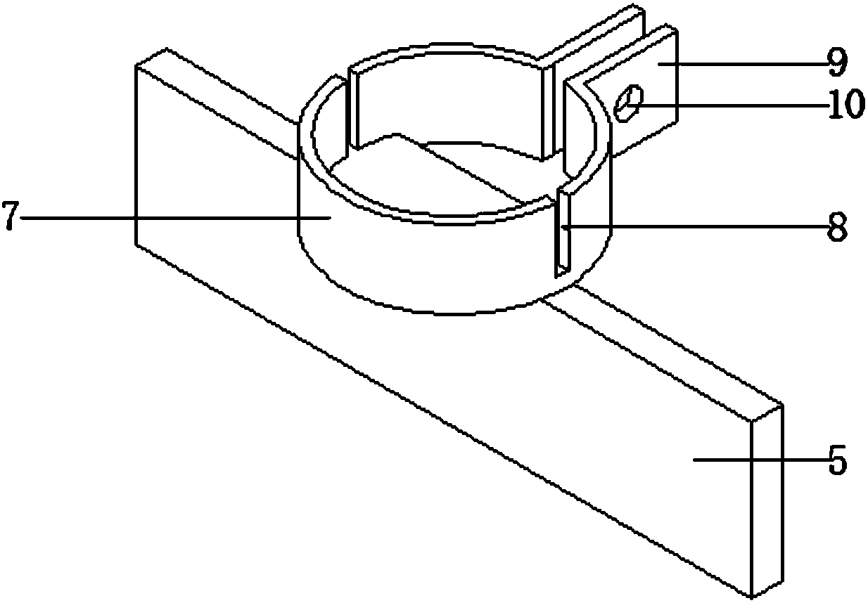
[0019] Such as figure 1 and figure 2 As shown, a stirring device for a slurry mixing tank includes a stirring shaft 1, which is provided with a first stirring paddle 2 and a second stirring paddle 3, and the first stirring paddle 2 is located on the side of the stirring shaft 1 The upper part, the second stirring paddle 3 is located at the lower part of the stirring shaft 1, the first stirring paddle 2 includes a first left paddle 21 and a first right paddle 22, the first right paddle 22 is provided with a positioning hole, the first The right paddle 22 is detachably connected to the first brush plate 4 through positioning holes and bolts. The end of the first brush plate 4 is provided with bristles, and the lower end of the stirring shaft 1 is provided with a second brush plate 5. The second brush plate 5 The ends are provided with bristle...


PUM


Abstract

The invention provides a stirring device for a slurry mixing tank. The stirring device comprises a stirring shaft, wherein the stirring shaft is provided with first stirring paddles and second stirring paddles; the first stirring paddles are located on the upper part of stirring shaft; the second stirring paddles are located on the lower part of stirring shaft; the first stirring paddles are composed of a first left paddle and a first right paddle; the first right paddle is provided with positioning holes and is detachably connected with a first brushing plate via the positioning holes and bolts; the end part of the first brushing plate is provided with brushing hair; the lower end of the stirring shaft is provided with a second brushing plate; and the end part of the second brushing plateis provided with brushing hair. The stirring device for the slurry mixing tank in the invention can prevent materials from depositing on the bottom of the tank and adhering onto the sidewall of the tank and improves the utilization rate of the materials.

Description

technical field [0001] The invention belongs to the technical field of water-based paint production equipment, and in particular relates to a stirring device for a slurry mixing tank. Background technique [0002] The mixing tank is a container used to mix and produce raw material mixtures. It is widely used in various work productions, especially in the production process of coatings and water-based paints. Due to the complex composition and different physical properties of the raw materials, the mixing tank performance is particularly important. In the design of the slurry tank, on the one hand, it is necessary to ensure that the tank has sufficient capacity and is easy to observe. On the other hand, the slurry tank is also very important for the dispersion and stirring of materials. The mixing tanks in the prior art are generally matched with the correct mixing module. However, since the mixing module fully considers the internal structure of the mixing tank and the char...

Claims


Application Information

Patent Timeline
Patent Type & Authority Applications(China)
IPC IPC(8): B01F7/00
CPCB01F27/091B01F27/191B01F27/2123
Inventor 李严
Owner TIANJIN DONGDING TECH CO LTD
Why Eureka
Try Eureka