
Kicker magnet power supply control system

A power control and magnet technology, applied in the field of control systems, can solve the problems of inconvenient application of large delay signals, delay length limitations, etc., and achieve the effect of overcoming the influence of ambient temperature, improving stability and efficiency, and realizing control requirements.

Inactive Publication Date: 2018-03-09
郭琳
View PDF0 Cites 3 Cited by
  • Summary
  • Abstract
  • Description
  • Claims
  • Application Information

AI Technical Summary

Problems solved by technology

But this method has obvious defects, because the delay length is limited, it is very inconvenient for applications that want to generate a large delay signal

Method used


Image

  • Kicker magnet power supply control system
  • Kicker magnet power supply control system
  • Kicker magnet power supply control system

Examples


Embodiment Construction

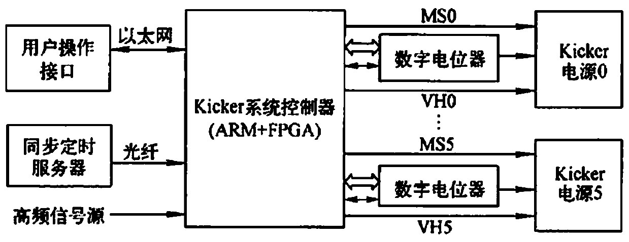
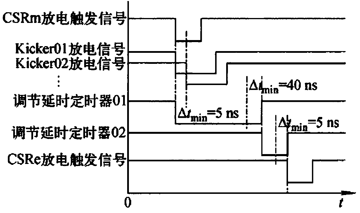
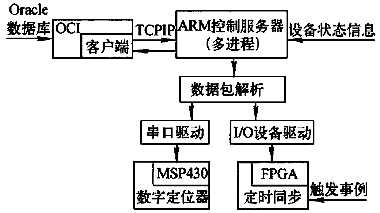
[0021] Such as figure 1 As shown, the Kicker magnet power control system is composed of Kicker system controller, digital potentiometer, Kicker power supply, synchronous timing server, user operation interface and other parts. In order to accurately grasp the injection and extraction timing of the beam current, accurately fine-tune the trigger signal of the Kicker power supply, use advanced embedded computer network and chip technology, and use the ARM+FPGA working mode to realize the timing control of the new kicker control system . Among them, the voltage setting for the Kicker power supply has also changed from the previous 12-bit DAC setting to the voltage setting using digital potentiometer (DCP) technology. The use of digital potentiometer and signal isolation circuit can effectively suppress the strong electromagnetic noise interference on site, and ensure that the voltage setting accuracy is 0.1%. MS is the trigger signal at the time of charging when kicking the rail...


PUM


Abstract

The invention provides a Kicker magnet power supply control system which comprises multiple injection and extraction links, the key is CSRM extraction and CSRE injection systems, and time control precision directly affects injection and extraction efficiency of beams. The advanced ARM+FPGA technology is used to realize precise control of a kicker power supply system, and the time control precisionreaches an ns level. An ARM mainly realizes the download and upload of control data, and the control timing of a kicker system is mainly accomplished through FPGA programming. Remote timing control signals are transmitted through an optical fiber, at the same time, the voltage giving of the kicker power supply is realized by using the digital potentiometer technology, and the giving precision reaches 0.1%.

Description

Technical field [0001] The invention relates to a control system, in particular to a Kicker magnet power control system. Background technique [0002] The kick rail system is an important part of HIRFL-CSR, which consists of kick rail magnets, high-voltage pulse power supply (Kicker power supply), timing control and trigger logic, reference voltage setting, waveform detection and other partsⅢ. The Kicker power supply system is a device that provides excitation current for the pulse magnet, and is also the control object of the Kicker control system. In order to extract the beam current in the ring with high efficiency, the discharge time of the Kicker power supply must be strictly synchronized with the bunch in the ring. To achieve this, there are usually two ways. The first one is to send the position information of the beam cluster in the ring to the Kicker system through the beam position detection device, which is more common in foreign countries, so that the Kicker con...

Claims


Application Information

Patent Timeline
Patent Type & Authority Applications(China)
IPC IPC(8): G05B19/042
CPCG05B19/0421
Inventor 郭琳
Owner 郭琳
Learn More