
Magnetron sputtering device and magnetic field distribution adjusting method thereof

A magnetron sputtering device and magnetic field distribution technology, applied in the field of magnetron sputtering, can solve the problems of sputtering film formation uniformity and stability adverse effects, limited improvement effect, lower product yield, etc., to achieve improvement in streak defects , Improve the target utilization rate and the effect of film formation uniformity

Active Publication Date: 2018-03-09
HEFEI XINSHENG OPTOELECTRONICS TECH CO LTD +1
View PDF6 Cites 7 Cited by
  • Summary
  • Abstract
  • Description
  • Claims
  • Application Information

AI Technical Summary

Problems solved by technology

The magnets used in planar targets are usually permanent magnets. After long-term use of the equipment, the position of the magnetic field generated by the permanent magnets on the surface of the planar target is relatively fixed, so that the local area of ​​the target surface affected by the magnetic field is sputtered for a long time. If the surface of the material is uneven, that is, there will be a high incidence of Target Mura (target spot or pattern), which will adversely affect the uniformity and stability of the sputtering film and reduce the product yield.
[0003] Moreover, as the size of the display panel continues to increase, the area of ​​the planar target increases accordingly, and the problem of low utilization of the target surface due to the long-term concentrated sputtering of the target surface is more serious.
[0004] In the prior art, the method of moving the target and / or the position of the magnet can reduce the speckle defect of the planar target to a certain extent and improve the uniformity of film formation, but the improvement effect is very limited

Method used


Image

  • Magnetron sputtering device and magnetic field distribution adjusting method thereof
  • Magnetron sputtering device and magnetic field distribution adjusting method thereof
  • Magnetron sputtering device and magnetic field distribution adjusting method thereof

Examples


Embodiment Construction

[0028] The following will clearly and completely describe the technical solutions in the embodiments of the present invention with reference to the accompanying drawings in the embodiments of the present invention. Obviously, the described embodiments are only some, not all, embodiments of the present invention. Based on the embodiments of the present invention, all other embodiments obtained by persons of ordinary skill in the art without making creative efforts belong to the protection scope of the present invention.

[0029] It should be noted that, unless otherwise defined, all terms (including technical and scientific terms) used in the embodiments of the present invention have the same meaning as commonly understood by those of ordinary skill in the art to which the present invention belongs. It should also be understood that terms such as those defined in common dictionaries should be interpreted as having meanings that are consistent with their meanings in the context o...


PUM


Abstract

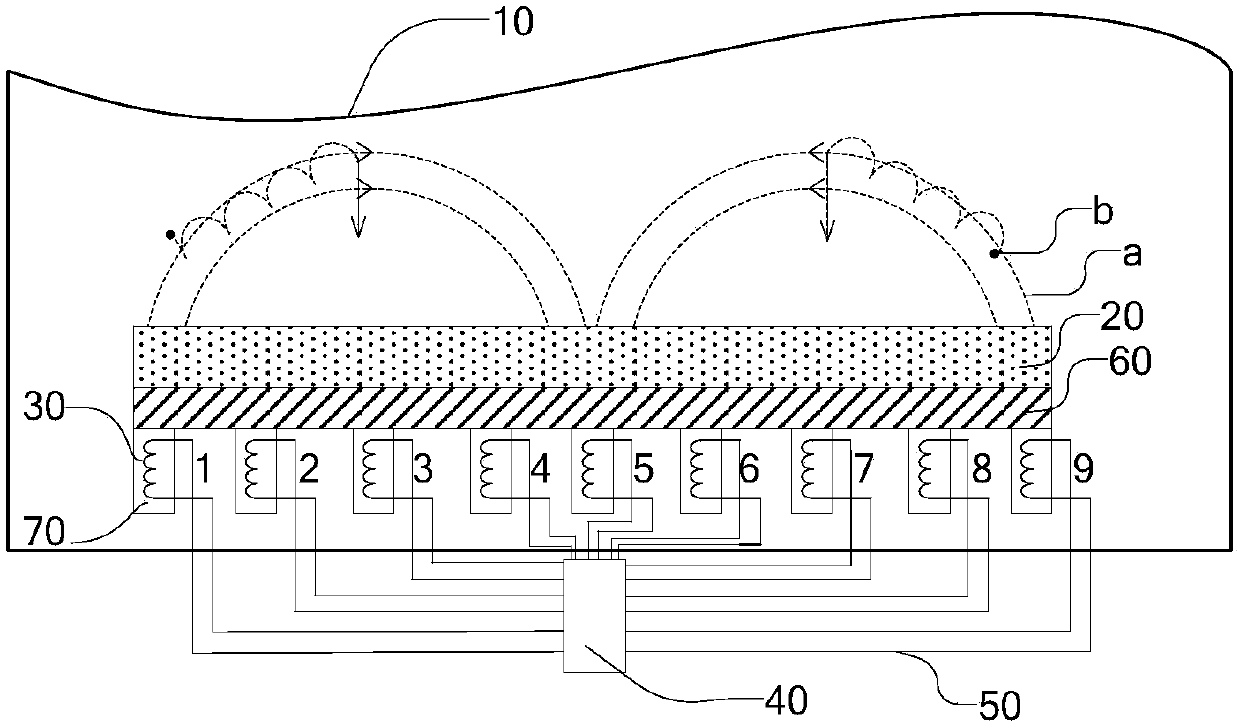
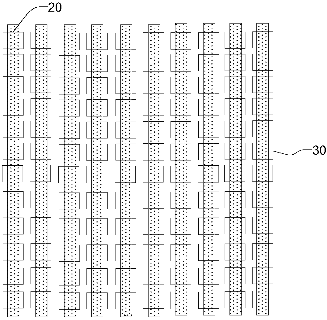
The invention provides a magnetron sputtering device and a magnetic field distribution adjusting method thereof, and relates to the field of magnetron sputtering. Poor stripes of a planar target material can be effectively improved, and the utilization rate of a target material and the film formation homogeneity can be improved. The magnetron sputtering device comprises a sputtering cavity, the planar target material, at least three sets of electromagnetic coils, a driving unit and connection wires, wherein the planar target material is arranged in the sputtering cavity; the at least three sets of electromagnetic coils are arranged on the part, away from one side being sputtered, of the planar target material, one end of each set of electromagnetic coil faces the planer target material, and the other end is away from the planar target material; the driving unit is configured to control on-off and magnetism direction of each set of electromagnetic coil; and the connection wires correspond to the three sets of electromagnetic coils one by one, and are configured to be electrically connected with the three sets of electromagnetic coils and the driving unit.

Description

technical field [0001] The invention relates to the field of magnetron sputtering, in particular to a magnetron sputtering device and a method for adjusting magnetic field distribution thereof. Background technique [0002] The film layer in a large-size display panel is usually prepared by a magnetron sputtering coating process, and a large-area metal or metal oxide film is formed by performing magnetron sputtering on a planar target. The magnets used in planar targets are usually permanent magnets. After long-term use of the equipment, the position of the magnetic field generated by the permanent magnets on the surface of the planar target is relatively fixed, so that the local area of ​​the target surface affected by the magnetic field is sputtered for a long time. If the surface of the material is uneven, that is, Target Mura (target spot or pattern) occurs frequently, which will adversely affect the uniformity and stability of sputtering film formation and reduce the pr...

Claims


Application Information

Patent Timeline
Patent Type & Authority Applications(China)
IPC IPC(8): C23C14/35C23C14/54
CPCC23C14/352C23C14/54
Inventor 胡迎宾袁广才赵策丁远奎李伟邵继峰
Owner HEFEI XINSHENG OPTOELECTRONICS TECH CO LTD
Learn More