Long-life high-temperature-resistant magnetic force improving type reactor control rod drive device
A drive mechanism and high-temperature-resistant technology, which is applied in the field of long-life high-temperature-resistant magnetic lift-type reactor control rod drive mechanisms to achieve the effects of reducing electromagnetic interference, improving safety and reliability, and improving temperature resistance levels
- Summary
- Abstract
- Description
- Claims
- Application Information
AI Technical Summary
Problems solved by technology
Method used
Image
Examples
Embodiment 1
[0041] as attached figure 2 As shown, the pressure-resistant casing assembly 3 of the present invention is divided into three sections according to its axial direction: it is composed of a suspension ring 7, a stroke sleeve 8 and a sealing casing 13, the sealing casing 13 is an integrated all-nickel-based structure, and the sealing casing 13 and the through No welds between pieces.
Embodiment 2
[0043] Similar to Example 1, as attached figure 2 As shown, threaded connection is adopted between the suspension ring 7 and the travel sleeve 8 . The stroke sleeve 8 and the sealing shell 13 are threadedly connected and welded with an "Ω" sealing ring 14 to realize sealing and anti-loosening. The Ω base material of the stroke sleeve 8 is nickel-based alloy welding ring 15, and the nickel-base alloy welding ring 15 is connected with the stroke sleeve 8 through nickel-base butt welding 16; Composed of two half-rings respectively, the locking band 12 binds the two half-rings of each magnetic conduction ring 9-11 symmetrically in the groove of the outer circle of the sealing shell 13 . The stroke sleeve 8 is an integral blind pipe structure with the upper end blocked.
Embodiment 3
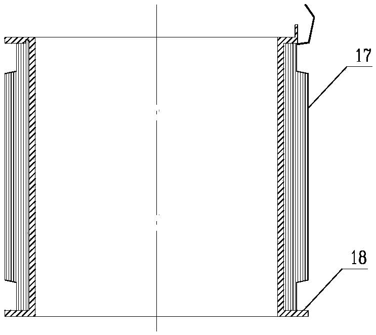
[0045] as attached image 3As shown, the armored coil in the coil assembly of the present invention is composed of an armored winding wire 17 and a bobbin 18 . The coil bobbin 18 is made of metal material, and its structure is a cylindrical structure with outer flanges at both ends. An annular groove is formed between the outer flanges, and the armored winding wire 17 is continuously wound in the annular groove. connector.
PUM
 Abstract
Description
Claims
Application Information
 - R&D Engineer
- R&D Manager
- IP Professional
- Industry Leading Data Capabilities
- Powerful AI technology
- Patent DNA Extraction
Browse by: Latest US Patents, China's latest patents, Technical Efficacy Thesaurus, Application Domain, Technology Topic, Popular Technical Reports.
© 2024 PatSnap. All rights reserved.Legal|Privacy policy|Modern Slavery Act Transparency Statement|Sitemap|About US| Contact US: help@patsnap.com


