


Quick Research
Generate reliable direction feasibility study reports for your R&D in just a few steps.

Technical Q&A
Discover and master advanced knowledge NOW. Basics, ideas, possibilities, all at once.

Find Solutions
As an expert in R&D theories, this can generate solutions to your technical problems instantly.

Evaluate Feasibility
Analyze your overall solution with one click, know your potential R&D risks in advance.

Monitor Landscape
Get weekly tech updates, stay abreast of the latest tech innovations and key insights.
Oil coating device
A technology of oiling device and oil inlet hole, which is applied in the field of parts spraying, and can solve the problems of slow oiling efficiency, environmental pollution, waste, etc.
- Summary
- Abstract
- Description
- Claims
- Application Information
AI Technical Summary
Problems solved by technology
Method used
Image

Examples
Embodiment 1
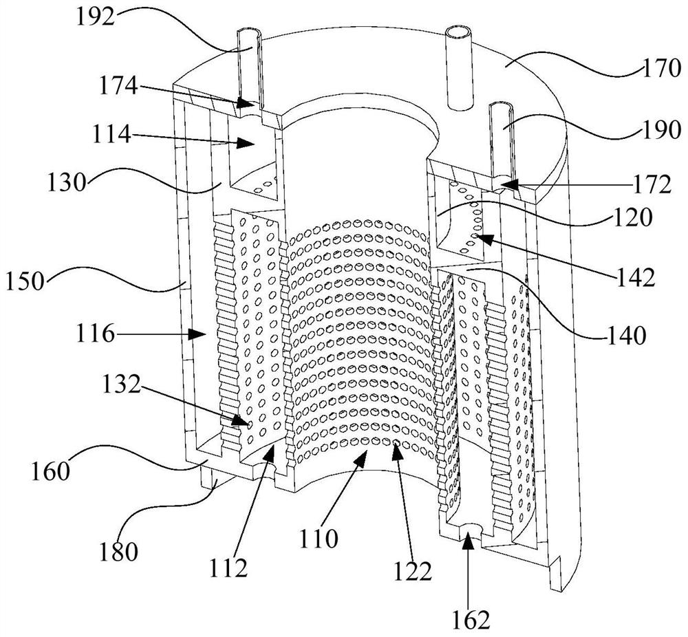
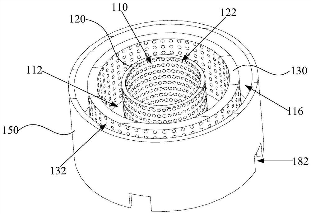
[0062] Such as figure 1 , figure 2 and image 3 As shown, the embodiment of the first aspect of the present invention provides an oiling device 100, the oiling device 100 includes: a body, the body includes: a first cavity 110 for placing parts; a flow channel 112, located in the first The peripheral side of the cavity 110, and communicates with the first cavity 110, the oil flows in the flow channel 112 along the direction of gravity; the injection part, connected with the body, is used to spray into the flow channel 112 toward the first cavity 110 flowing airflow.
[0063] In the oiling device 100 provided by the present invention, the oiling device 100 includes a main body and a spraying part. The body is the main frame structure of the oiling device 100 , on the one hand, it is used to enclose the working cavity, and on the other hand, it is used to position and support other structures on the oiling device 100 . Specifically, a first cavity 110 and a flow channel 112...
Embodiment 2
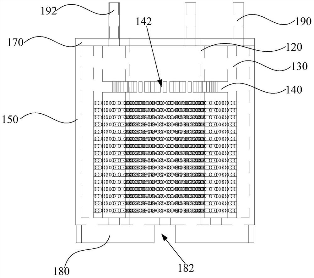
[0068] Such as figure 1 , figure 2 and Figure 4 As shown, in the embodiment of the second aspect of the present invention, the body further includes: a second cavity 114; an oil inlet hole 142 communicating with the flow channel 112 and the second cavity 114; an oil outlet hole 162 communicating with the flow channel 112 Wherein, in the height direction of the oiling device 100, the flow channel 112 is located between the oil inlet hole 142 and the oil outlet hole 162.
[0069] In this embodiment, the structure related to the flow channel 112 is described in detail. Specifically, a second cavity 114 , an oil inlet and an oil outlet 162 are also formed in the body. The second cavity 114 is located at the top of the flow channel 112 , and one end of the oil inlet hole 142 communicates with the bottom of the second cavity 114 , and the other end communicates with the top of the flow channel 112 , so that the oil can flow in through the oil inlet hole 142 The second cavity 1...
Embodiment 3
[0071] Such as figure 1 , figure 2 and Figure 4 As shown, in the embodiment of the third aspect of the present invention, there are multiple oil inlet holes 142 , and the multiple oil inlet holes 142 are arranged around the first cavity 110 .
[0072] In this embodiment, a plurality of oil inlet holes 142 are formed on the body, and the plurality of oil inlet holes 142 are all arranged on the peripheral side of the first cavity 110 and arranged around the first cavity 110 . Specifically, a plurality of oil inlet holes 142 are arranged at intervals and distributed on the same level. By arranging a plurality of oil inlet holes 142 distributed around the first cavity 110 on the peripheral side of the first cavity 110 , the oil flowing into the plurality of oil inlet holes 142 can be combined to form an oil curtain. The shape of the oil curtain corresponds to the distribution shape of the plurality of oil inlet holes 142 on the horizontal plane. Thus, an oil curtain surround...
PUM
 Abstract
Description
Claims
Application Information
 - R&D Engineer
- R&D Manager
- IP Professional
- Industry Leading Data Capabilities
- Powerful AI technology
- Patent DNA Extraction
Browse by: Latest US Patents, China's latest patents, Technical Efficacy Thesaurus, Application Domain, Technology Topic, Popular Technical Reports.
© 2024 PatSnap. All rights reserved.Legal|Privacy policy|Modern Slavery Act Transparency Statement|Sitemap|About US| Contact US: help@patsnap.com