Spraying machine and spraying system provided with same
The technology of spraying machine and spraying gun is applied in the direction of construction and building structure, which can solve the problem of low working efficiency of waterproof coating, and achieve the effect of improving working efficiency.
- Summary
- Abstract
- Description
- Claims
- Application Information
AI Technical Summary
Problems solved by technology
Method used
Image
Examples
Embodiment 1
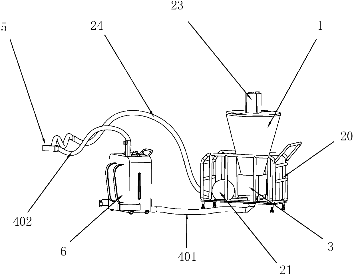
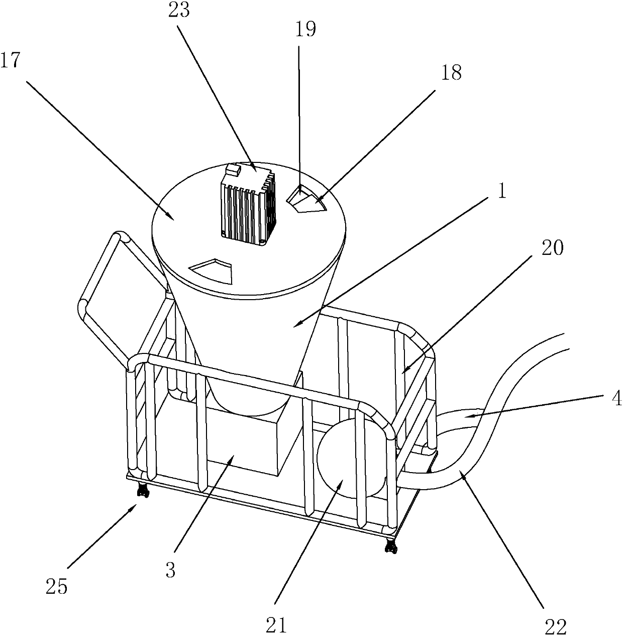
[0037] Such as figure 1 As shown, a spraying machine includes a barrel 1, the barrel 1 is provided with a motor 23 for controlling the work of the barrel 1, and the bottom of the barrel 1 is connected with a waterproof slurry for extruding the inside of the barrel 1 Extrusion pump 3. A discharge pipe 4 is arranged below the extrusion pump 3 , and the discharge pipe 4 is connected to the feed box 6 , and the feed box 6 divides the discharge pipe 4 into two parts: a feed pipe 401 and a spray pipe 402 . One end of the spray pipe 402 is connected to the feed box 6 , and the other end is connected to the spray gun 5 . The spray gun is also connected with a pressure supply pipe 24, and the other end of the pressure supply pipe 24 is connected to the compressor 21, and the compressor 21 is placed on the left side of the barrel 1;
[0038] When starting the spraying work: first add waterproof paint raw materials into the material barrel 1, then start the motor 23, so that the waterp...
Embodiment 2
[0041] Such as figure 2Shown, a kind of spraying machine, and the difference of embodiment one is that the feeding box 6 is provided with some spraying material interfaces 12 for connecting the spraying pipe 402, and the spraying material interfaces 12 in the unused state are all sealed with a sealing cover 13 seal. The sealing cover 12 and the material injection interface 12 are connected together by threads. The sealing cover 13 is provided with a material injection column 15, and the material injection column 15 is provided with an injection port 16 for connecting the spray gun 5. The outward end surface of the sealing cover 13 is provided with a rotating protrusion 14 for people to grasp;
[0042] When the spraying range is small, there is no need to hold the spray gun 5 for spraying work, just push the feed box 6 and move while spraying, and when spraying in a higher place, there is no need to hold the spray gun 5 by hand, just adjust the spray gun 5 The height of mat...
Embodiment 3
[0044] Such as figure 2 Shown, a kind of spraying machine, the difference with embodiment one is that the side of feeding box is provided with the shoulder belt 8 that is carried on the back by the master of spraying, also is provided with on the feeding box 6 and is used for restraining the belt 9 of the waist of spraying master, Also be provided with the scale table 7 that is used to observe the waterproof slurry margin inside feed box 6. Shoulder belt 8 and scale table 7 are not in the same side of feed box 6.
PUM
 Abstract
Description
Claims
Application Information
 - R&D
- Intellectual Property
- Life Sciences
- Materials
- Tech Scout
- Unparalleled Data Quality
- Higher Quality Content
- 60% Fewer Hallucinations
Browse by: Latest US Patents, China's latest patents, Technical Efficacy Thesaurus, Application Domain, Technology Topic, Popular Technical Reports.
© 2025 PatSnap. All rights reserved.Legal|Privacy policy|Modern Slavery Act Transparency Statement|Sitemap|About US| Contact US: help@patsnap.com


