Screen printing plate

A screen printing plate and mesh technology, applied in printing, printing plate, printing process, etc., can solve the problems of not considering breakage, not giving, etc.

Inactive Publication Date: 2018-03-06
KOBELCO RES INST
View PDF7 Cites 0 Cited by
  • Summary
  • Abstract
  • Description
  • Claims
  • Application Information

AI Technical Summary

Problems solved by technology

In addition, in the above-mentioned techniques, the problem of fracture is not considered, nor is there any suggestion on increasing or decreasing the tension in either direction in order to avoid fracture.

Method used


Image

  • Screen printing plate
  • Screen printing plate
  • Screen printing plate

Examples


Embodiment approach 1

[0062]

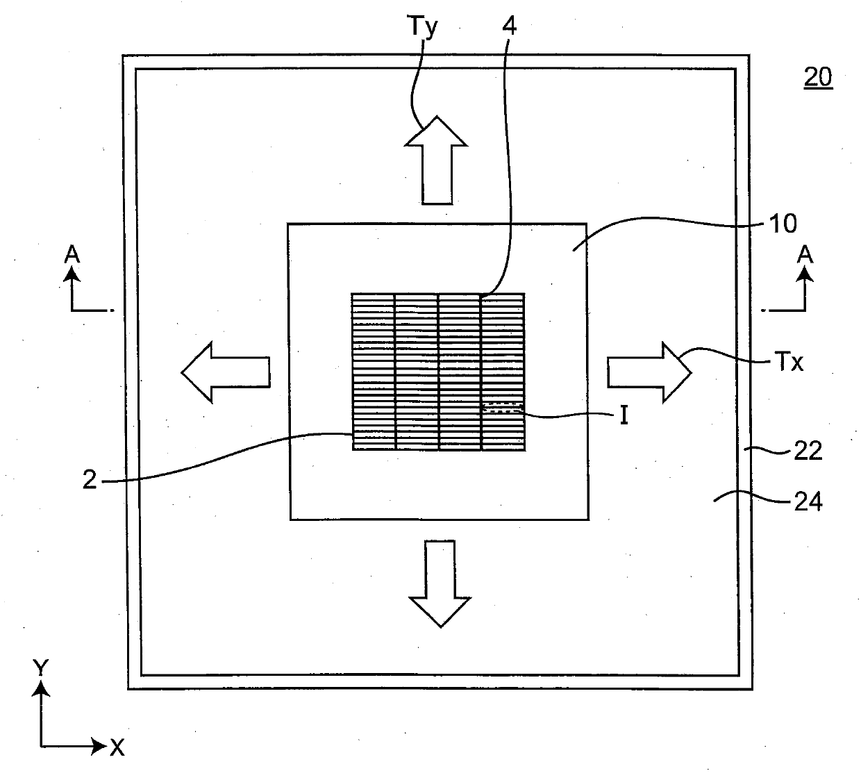
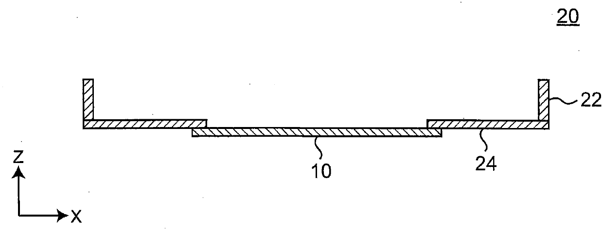
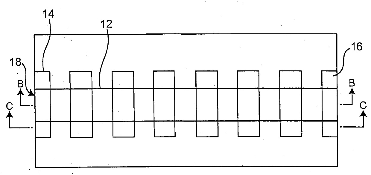
[0063] figure 1 It is a plan view showing the outline of the screen printing plate 20 according to the first embodiment. figure 2 is along figure 1 A brief cross-sectional view viewed from the A-A direction. Figure 3A yes figure 1 A partial enlarged plan view of the region I of the finger electrode pattern of the screen printing plate.

[0064] Such as figure 1 , figure 2 As shown, in this screen printing plate 20 , the above-mentioned rolled metal foil mesh member 10 is disposed on an aluminum frame 22 via a mesh fabric 24 or the like woven with polyester thin threads. The screen printing plate 20 has: the above-mentioned rolled metal foil mesh member; Figure 3A Resin 16 covering a plurality of openings 14 arranged along one direction; and line pattern 18 formed by opening and dividing resin 16 with a width ranging from 10 μm to 60 μm are shown. The longitudinal direction of the line pattern 18 is one direction, and the line pattern 18 is provided over t...


PUM


Abstract

The present invention relates to a screen printing plate using a metal foil mesh member having openings formed in a metal foil having the thickness not less than 5 um and not more than 25 um, and provides a screen printing plate in which the metal foil mesh member is hardly broken. The screen printing plate comprises: the metal foil mesh member having a plurality of openings arranged along one direction of the metal foil having the thickness not less than 5 um and not more than 25 um, and having a pattern for a finger electrode to install finger electrodes; and a resin covering a part of the openings, wherein the metal foil mesh member is supported so that the tensile force along the direction perpendicular to one direction is smaller than the tensile force along one direction in which theopenings of the pattern for the finger electrode extend.

Description

technical field [0001] The present invention relates to a screen printing plate used when forming collector electrodes on the surface and back of a solar cell or performing screen printing in other applications. Background technique [0002] In a solar cell, the more electrons and positive hole pairs generated by sunlight, the higher its power generation performance. In order to increase the generation of electrons and positive hole pairs, it is necessary to increase the sunlight received in the solar cell. On the other hand, in order to collect the generated electrons and positive holes, it is necessary to arrange a collector electrode called a finger electrode on the light-receiving surface of sunlight. However, since sunlight is shielded at the position where the finger electrodes are arranged, it is necessary to reduce the width of the finger electrodes as much as possible to reduce the sunlight shielding area. [0003] For the reasons described above, the thinning of ...

Claims


Application Information

Patent Timeline
Patent Type & Authority Applications(China)
IPC IPC(8): B41N1/24
CPCB41N1/24B41N1/247B41N1/248B41N1/04
Inventor 福田正人宫田浩一筱田达昭
Owner KOBELCO RES INST
Why Eureka
Try Eureka