Cabling yarn binding machine with stranding mold

A skeining machine and mold technology, which is applied in the fiber mechanical structure, light guide, optics, etc., can solve the problems of low service life of the stranding die and the influence of the overall roundness of the stranding die, so as to ensure the roundness and improve the use. Longevity and effect of improving wear resistance

Pending Publication Date: 2018-03-02
SHANDONG PACIF OPTICS FIBER & CABLE CO LTD
View PDF6 Cites 2 Cited by
  • Summary
  • Abstract
  • Description
  • Claims
  • Application Information

AI Technical Summary

Problems solved by technology

[0005] In order to overcome the problem that the overall roundness of the stranding die is affected by the non-directional wear of the yarn on the stranding die as pointed out above, which in turn leads to the low service life of the stranding die, the present invention provides a Cable binding machine with mold

Method used


Image

  • Cabling yarn binding machine with stranding mold
  • Cabling yarn binding machine with stranding mold
  • Cabling yarn binding machine with stranding mold

Examples


Embodiment Construction

[0027] The present invention will be further described below in conjunction with specific examples.

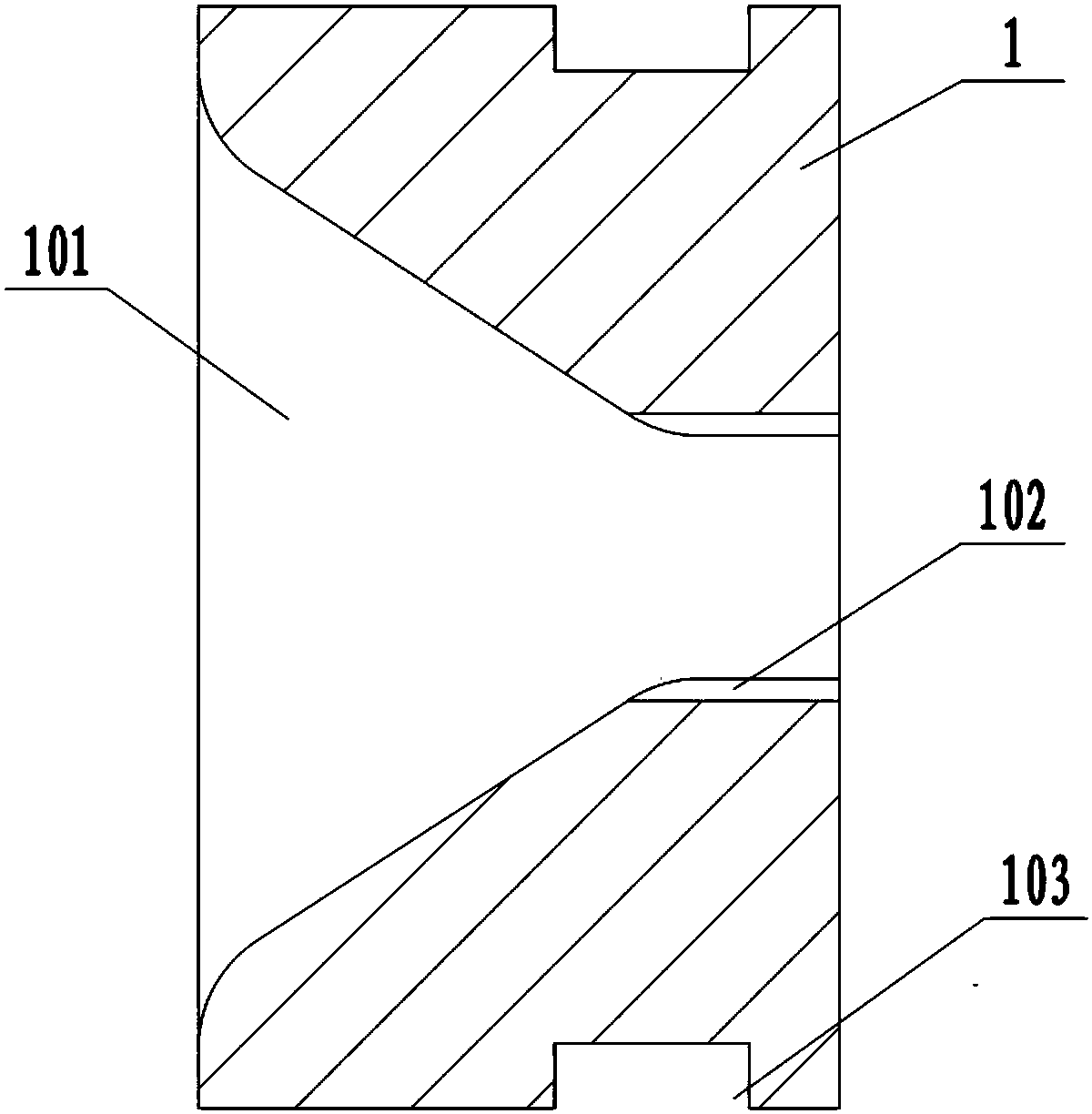
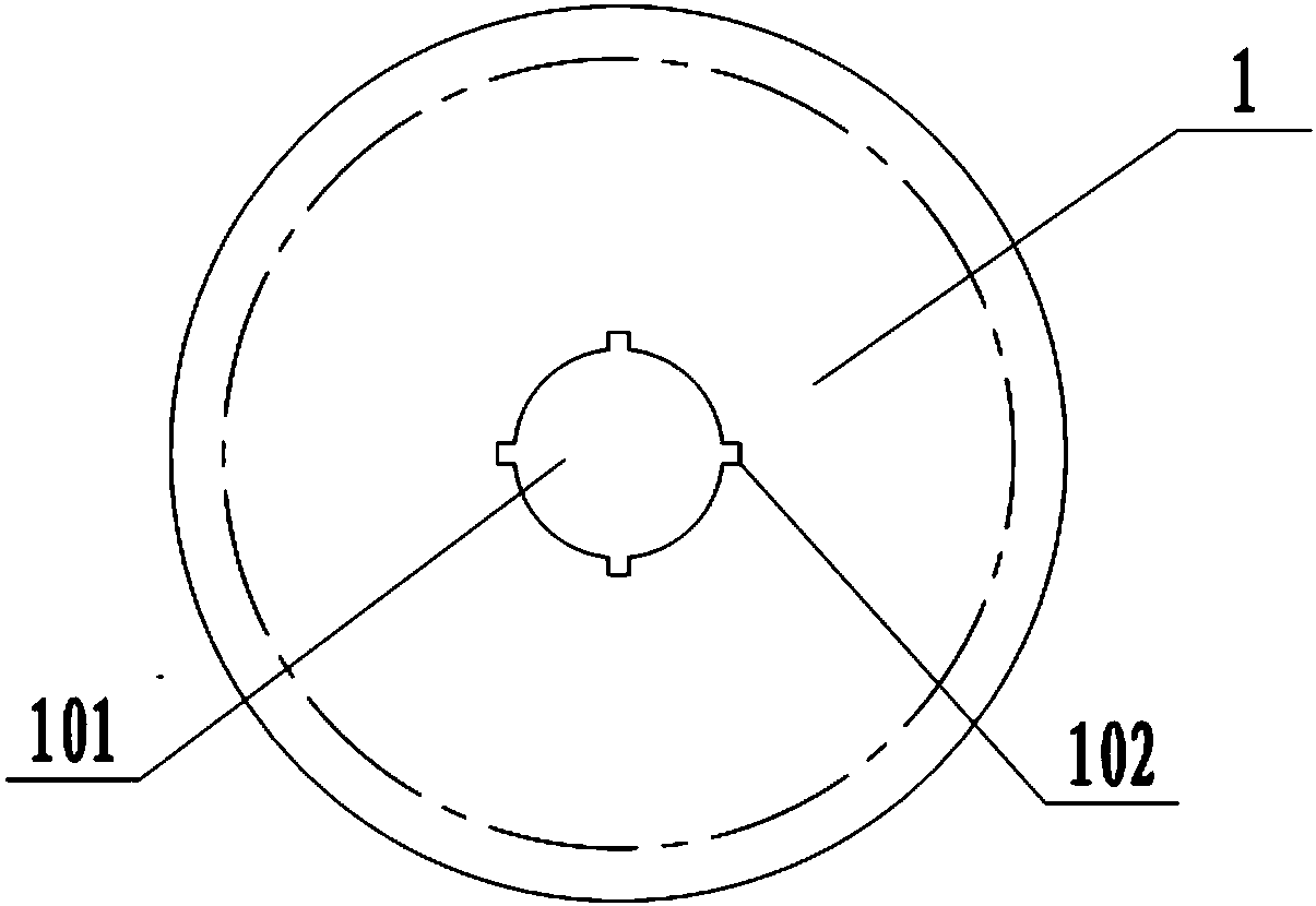
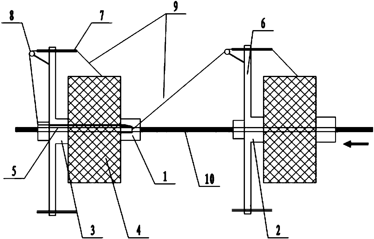
[0028] Such as Figure 1-Figure 3 As shown, a cable binding machine with a twisting mold includes a frame and a mold body, and the first hollow rotating shaft 2 and the second hollow rotating shaft 3 driven by a driving device are installed in rotation on the frame, The driving device can be driven by a driving motor to realize the opposite rotation of the first hollow rotating shaft 2 and the second hollow rotating shaft 3. Since the driving motor drives the rotating shaft to rotate, it is a conventional technical means in the prior art, which is recognized by those skilled in the art. Therefore, it will not be described in detail here. The first hollow rotating shaft 2 and the second hollow rotating shaft 3 are correspondingly arranged, and yarn clusters 4 are wound on the first hollow rotating shaft 2 and the second hollow rotating shaft 3, and the mold body 1 is installed ...


PUM


Abstract

The invention belongs to the technical field of optical cable manufacturing equipment, and provides a cabling yarn binding machine with a novel stranding mold. The cabling yarn binding machine comprises a machine frame and a mold body, and is characterized in that the mold body is provided with a beam cable channel for a cable core to pass, the cross section of the beam cable channel is circular,the inner wall of the mold body is provided with at least one yarn guiding slot, chamfers of the yarn guiding slots are set in a polished manner, the mold body is arranged at the end, which is close to a first hollow rotating shaft, of a second hollow rotating shaft, a small-opening end of the beam cable channel is arranged in a mode of facing towards the first hollow rotating shaft, the first hollow rotating shaft is internally provided with an in-shaft yarn guiding pipe, and the in-shaft yarn guiding pipe is communicated with the beam cable channel. The cabling yarn binding machine realizesdirectional abrasion for the stranding mold, does not cause influences for the roundness of the stranding mold after long-time use and improves the service life of the stranding mold.

Description

technical field [0001] The invention relates to the technical field of optical cable manufacturing equipment, in particular to a cable binding machine with a twisting mold. Background technique [0002] With the continuous development of the communication industry, the demand for optical cables is growing rapidly, and the structure of optical cables is gradually developing in the direction of diversification and specialization. The stranding of optical cables is an important process in the manufacturing process of optical cables. The tube or filling rope is rotated and twisted together around the central reinforcement, and then tied and fixed with tying yarn to form a stable and round cable core, and then add some protective auxiliary materials, such as ointment, water-blocking yarn, water-blocking Tape, etc., to enhance the flexibility and bendability of the optical cable, improve the tensile capacity of the optical cable and improve the temperature characteristics of the o...

Claims


Application Information

Patent Timeline
Patent Type & Authority Applications(China)
IPC IPC(8): G02B6/44
CPCG02B6/4479
Inventor 李学保马敬磊齐伟李广省
Owner SHANDONG PACIF OPTICS FIBER & CABLE CO LTD
Why Eureka
Try Eureka