Circular loom

A circular loom, host technology, applied to the circular loom. It can solve the problems of increasing the use cost of limit rollers and affecting the efficiency of circular looms, and achieve the effects of reducing wear, alleviating impact and improving weaving efficiency.

Pending Publication Date: 2018-11-13
雁峰集团有限公司
View PDF17 Cites 1 Cited by
  • Summary
  • Abstract
  • Description
  • Claims
  • Application Information

AI Technical Summary

Problems solved by technology

Using a slope to limit the position of the shuttle requires installing a limit roller on the shuttle, so the loss of the limit roller will increase the cost of use, and at the same time, frequent replacement of the limit roller will also affect the efficiency of the circular loom

Method used


Image

  • Circular loom
  • Circular loom
  • Circular loom

Examples


Embodiment Construction

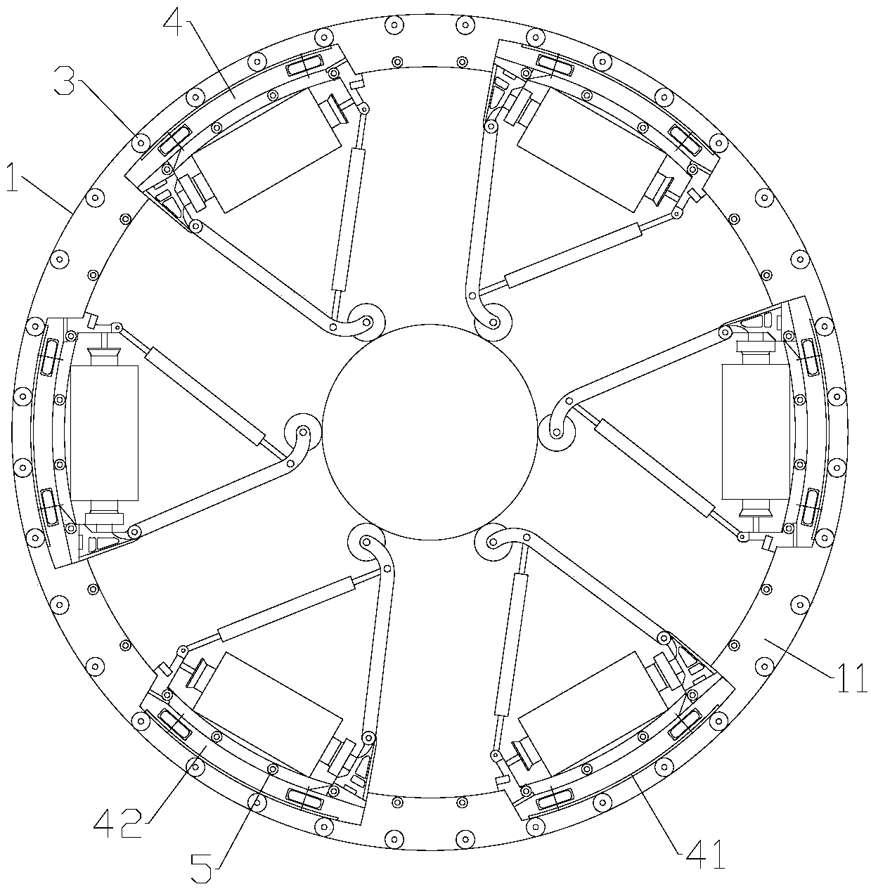
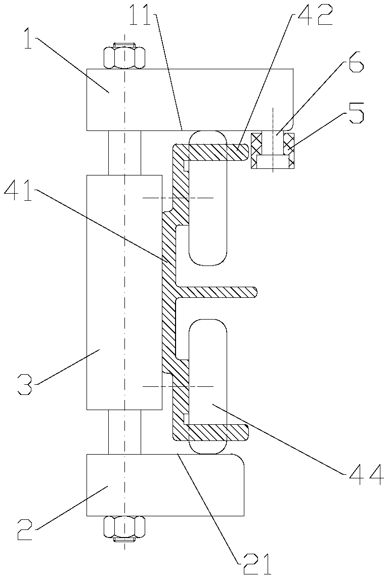
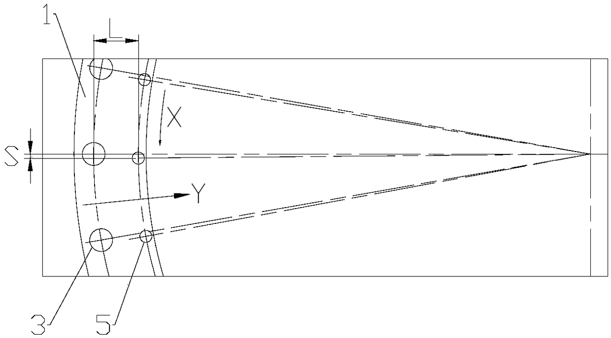
[0021] The invention provides a circular loom, comprising a frame, a main frame, a door ring assembly and a shuttle, and the main frame and the door ring assembly are arranged on the frame, such as figure 1 and figure 2 As shown, the door ring assembly includes an upper door ring 1, a lower door ring 2 and a plurality of rollers 3 connected to the upper door ring 1 and the lower door ring 2. The plurality of rollers 3 form a rolling track in a circle, and the host drives the shuttle 4 Make a circular motion along the rolling track. In the present embodiment, the shuttle 4 is provided with six and evenly distributed on the rolling track. The shuttle 4 includes a shuttle body 41, and the lower surface 11 of the upper door ring 1 and the upper surface 21 of the lower door ring 2 are On the radial plane, the lower surface 11 of the upper door ring 1 is provided with an anti-off roller 5 on the inner ring side of the running track of the shuttle 4, and the upper side of the shuttl...


PUM


Abstract

The invention discloses a circular loom, belongs to the field of plastic weaving machinery, and solves the problem of high using cost of shuttle derailment preventing in the prior art. The circular loom is characterized in that derailment preventing wheels are arranged on part, located on the inner circle side of the operating trajectory of the shuttle, of the lower surface of an upper door ring,upper protruded edges which protrude towards the center of the circular loom are arranged on the upper side of the shuttle, the upper protruded edges extend towards the back from the front end of theshuttle, the upper protruded edges are located on the same horizontal height of the derailment preventing wheels, gaps are reserved between the upper protruded edges and the derailment preventing wheels, multiple derailment preventing wheels are distributed in the circumferential direction of the upper door ring, and the spacing between the two adjacent derailment preventing wheels is not greaterthan the extending lengths of the upper protruded edges. The circular loom is mainly used for effectively preventing the derailment of the shuttle.

Description

technical field [0001] The invention relates to a plastic weaving machine, especially a circular loom. Background technique [0002] In the existing plastic circular loom, the main machine drives the shuttle to run on the track formed by the door ring assembly to realize the weft weaving. Since the running speed of the shuttle is relatively fast, it can reach more than 100 revolutions per minute. In order to prevent the shuttle from detaching from the track Generally, a bevel is set on the door ring assembly, and the bevel is used to limit the position of the shuttle to prevent the shuttle from deviating from the track. . If the inclined position is used to limit the shuttle, it is necessary to install limit rollers on the shuttle. Therefore, the loss of the limit rollers will increase the cost of use. At the same time, frequent replacement of the limit rollers will also affect the efficiency of the circular loom. Contents of the invention [0003] The object to be achie...

Claims


Application Information

Patent Timeline
Patent Type & Authority Applications(China)
IPC IPC(8): D03D37/00
CPCD03D37/00
Inventor 陈志淡陈卫国邹虎生陈崇斌梁海立吴阳春段李平
Owner 雁峰集团有限公司
Why Eureka
Try Eureka