
Membrane tension control device for stacking machine

A tension control and lamination machine technology, applied in the field of manufacturing equipment, can solve the problems of affecting quality, diaphragm wrinkling, tearing diaphragm, etc., to achieve high precision, constant tension and good stability.

Pending Publication Date: 2018-03-02
东莞市沈海自动化科技有限公司
View PDF0 Cites 2 Cited by
  • Summary
  • Abstract
  • Description
  • Claims
  • Application Information

AI Technical Summary

Problems solved by technology

[0002] The tension of the diaphragm in the traditional stacking machine cannot be kept constant. During lamination, the positive and negative electrodes are stacked alternately. The diaphragm adopts Z-shaped feeding to separate the positive and negative electrodes. The diaphragm feeding mechanism and the stacking table will have relative displacement. The distance between the diaphragm feeding place and the stacking table will change from large to small. In this process, if the tension of the diaphragm is not controlled, the speed of the diaphragm tension change cannot keep up with the lamination speed, resulting in stacking The diaphragm on the pole piece is uneven, the diaphragm is wrinkled, or even torn off, which affects the quality

Method used


Image

  • Membrane tension control device for stacking machine
  • Membrane tension control device for stacking machine
  • Membrane tension control device for stacking machine

Examples


Embodiment Construction

[0035] The present invention will be further described below in conjunction with specific embodiments and accompanying drawings.

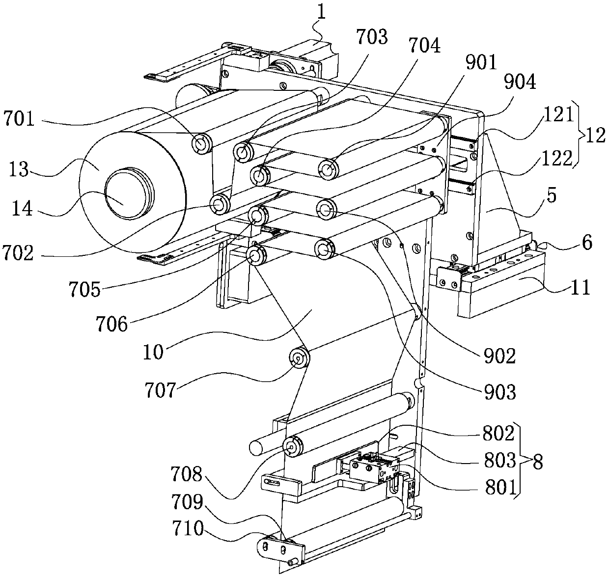
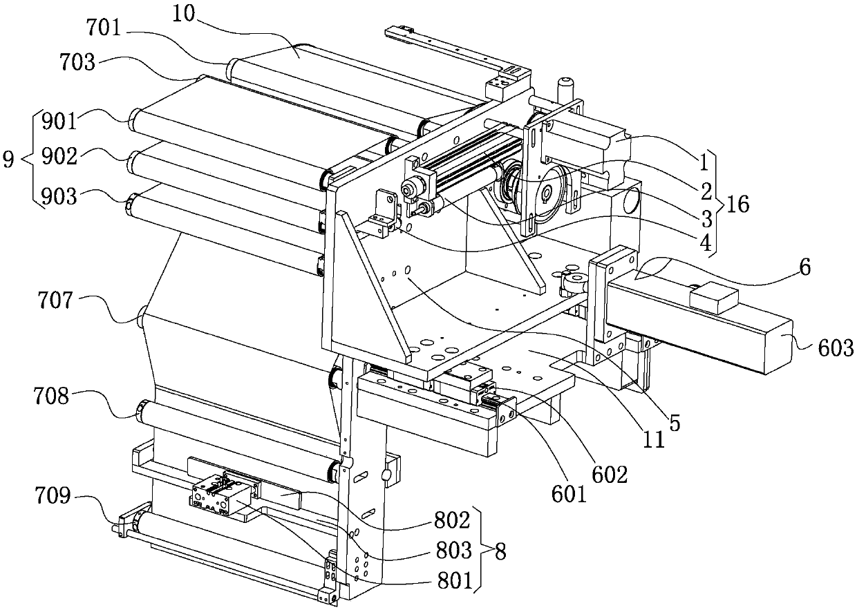
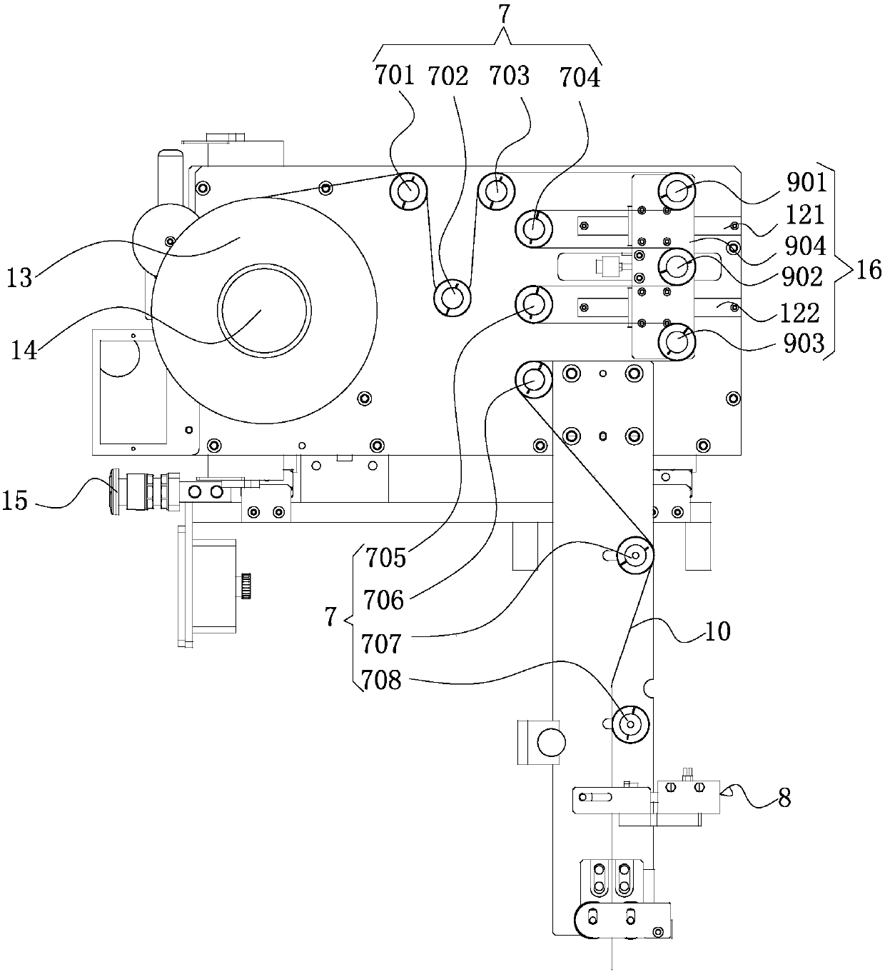
[0036] See Figure 1-3 As shown, it is a diaphragm tension control device for a laminated machine, which includes: a base 11, a riser assembly 5 mounted on the base 11, a servo motor 1 arranged on the riser assembly 5, a 5 and connected to the servo motor 1, the roller set 7 installed on the vertical plate assembly 5 and used to guide the diaphragm 10, the diaphragm tension control device of the stacker also includes a diaphragm tension control mechanism 16. The diaphragm tension control mechanism 16 includes the guide slide rail 12 installed on the front end of the vertical plate assembly 5, the moving seat 904 installed on the guide slide rail 12 and the floating roller group 9 installed on the moving seat 904, and the vertical plate assembly 5 rear end and is used to drive the cylinder 3 of the moving seat 904 and the floating roller group 9 to...


PUM


Abstract

The invention discloses a membrane tension control device for a stacking machine. The membrane tension control device for the stacking machine comprises a base, a vertical plate assembly mounted on the base, a servo motor arranged on the vertical plate assembly, a membrane winding drum shaft mounted on the vertical plate assembly and connected with the servo motor, and a passing roller set used for guiding membranes and further comprises a membrane tension control mechanism. The membrane tension control mechanism comprises a guiding sliding rail mounted at the front end of the vertical plate assembly, a moving seat mounted on the guiding sliding rail, a floating roller set mounted on the moving seat, an air cylinder mounted at the rear end of the vertical plate assembly and used for driving the moving seat and the floating roller set to move on the guiding sliding rail, a potentionmeter and a pressure regulating valve mounted between the air cylinder and the moving seat. In the membrane tension control device of the stacking machine, the tension of the membranes is kept constant through the membrane tension control mechanism, the tension changing speed of the membranes keeps pace with the stacking speed, accordingly, the membranes stacked on pole pieces are flat and not liable to wrinkle, and are prevented from being pulled apart, and thus the quality is improved.

Description

Technical field: [0001] The invention relates to the field of manufacturing equipment, in particular to a diaphragm tension control device for a lamination machine. Background technique: [0002] The tension of the diaphragm in the traditional stacking machine cannot be kept constant. The positive and negative electrodes are stacked alternately during stacking. The diaphragm adopts Z-shaped feeding to separate the positive and negative electrodes. The diaphragm feeding mechanism and the stacking table will have relative displacement. The distance between the diaphragm discharge place and the stacking table will change from large to small. In this process, if the tension of the diaphragm is not controlled, the speed of the diaphragm tension change cannot keep up with the lamination speed, resulting in stacking The diaphragm on the pole piece is uneven, wrinkled, or even torn off, which affects the quality. [0003] In view of this, the inventor proposes the following technic...

Claims


Application Information

Patent Timeline
Patent Type & Authority Applications(China)
IPC IPC(8): B65H23/185B65H23/182B65H23/26B65H23/34B65H23/032H01M10/04
CPCH01M10/0404B65H23/0324B65H23/1825B65H23/185B65H23/26B65H23/34B65H2701/1133Y02P70/50
Inventor 崔海冰
Owner 东莞市沈海自动化科技有限公司
Learn More