
Driving circuit for dynamic variable IGBT switching characteristics and protection method thereof

A technology of switching characteristics and driving circuits, which is applied in the direction of adjusting electrical variables, control/regulation systems, instruments, etc., can solve the problems of unable to meet the control performance and protection requirements of high-power IGBT, single form, etc., and achieve enhanced fault analysis and Handling ability, suppression of overvoltage and overcurrent, and effect of reducing switching loss

Active Publication Date: 2018-02-27
CHINA ACADEMY OF RAILWAY SCI CORP LTD +2
View PDF7 Cites 5 Cited by
  • Summary
  • Abstract
  • Description
  • Claims
  • Application Information

AI Technical Summary

Problems solved by technology

The underlying protection of the IGBT is mainly accomplished through the "analog drive circuit", which has a single form and a single protection level; for high-power IGBT drive circuits, the drive protection scheme is mostly "controller + analog pulse distribution circuit + analog drive circuit"
Compared with the low-power level driving scheme, an "analog pulse distribution circuit" is added, but this level of circuit generally does not have a protection function or has a single protection function
[0004]In addition, the traditional IGBT driver composed of analog circuits cannot intelligently and dynamically control the IGBT on-off process and has a single protection strategy, which cannot meet the control performance of high-power IGBTs and protection requirements

Method used


Image

  • Driving circuit for dynamic variable IGBT switching characteristics and protection method thereof
  • Driving circuit for dynamic variable IGBT switching characteristics and protection method thereof
  • Driving circuit for dynamic variable IGBT switching characteristics and protection method thereof

Examples


Embodiment Construction

[0031] The following will clearly and completely describe the technical solutions in the embodiments of the present invention with reference to the accompanying drawings in the embodiments of the present invention. Obviously, the described embodiments are only some, not all, embodiments of the present invention. Based on the embodiments of the present invention, all other embodiments obtained by persons of ordinary skill in the art without making creative efforts belong to the protection scope of the present invention.

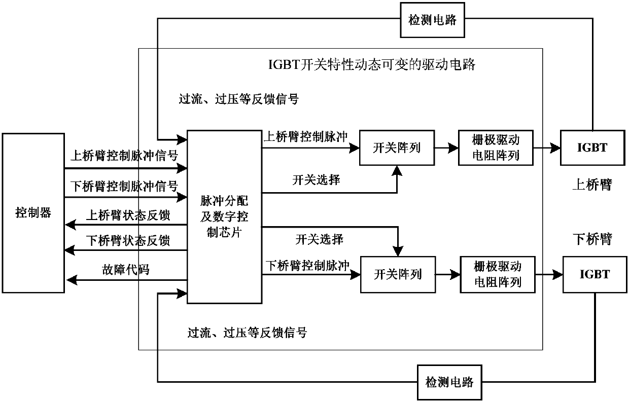
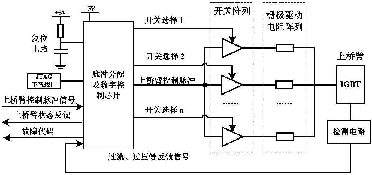
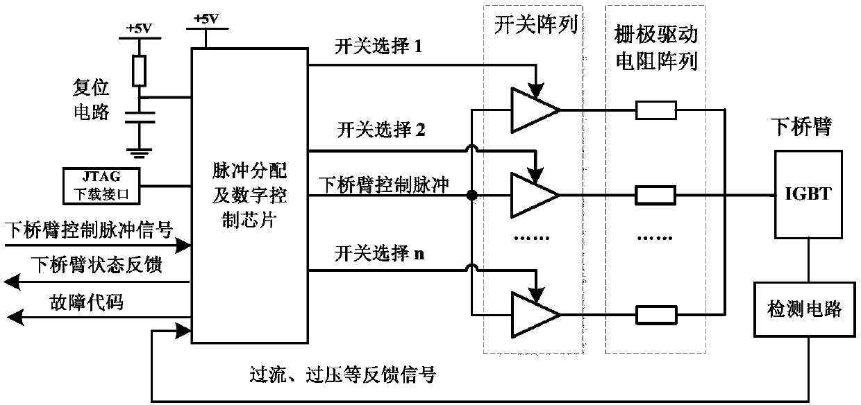
[0032] After research, the switching performance and loss of IGBT are affected by the gate drive resistance, especially in the turn-on and turn-off transient process, it is necessary to quickly adjust the size of the gate drive resistance to achieve the rational distribution of loss, overvoltage and overcurrent; at the same time In the fault state, the IGBT can also be actively protected by adjusting the size of the gate drive resistor. In addition, in order t...


PUM


Abstract

Provided are a driving circuit for dynamic variable IGBT switching characteristics and a protection method thereof. The driving circuit for dynamic variable IGBT switching characteristics includes a pulse distribution and digital control chip, switch arrays and gate driving resistance arrays; the pulse distribution and digital control chip is connected with the input end of an IGBT upper bridge arm through a part of the switch arrays and a part of the gate driving resistance arrays, and connected with the input end of an IGBT lower bridge arm through the rest switch arrays and the rest gate driving resistance arrays; the pulse distribution and digital control chip receives the control pulse signals of a controller, receives status information fed back by the IGBT upper bridge arm and the IGBT lower bridge arm, outputs control pulse to drive the IGBT upper bridge arm and the IGBT lower bridge arm after completing pulse distribution, pulse self-locking, pulse interlocking and other treatments according to the control pulse signals and the status information, and meanwhile controls the switch arrays to dynamically change gate driving resistances. The switching characteristics are optimized, the switching loss is reduced, and besides, malfunction coding can be fed back to the controller so as to facilitate intelligent malfunction diagnosis.

Description

technical field [0001] The invention relates to the technical field of power electronics, in particular to a driving circuit and a protection method with dynamically variable switching characteristics of an IGBT. Background technique [0002] The insulated gate bipolar transistor (Insulated Gate Bipolar Transistor, IGBT) is the core device of the power module in the traction auxiliary converter of the high-speed train. As the interface circuit between the power circuit and the controller, the IGBT driver has a great impact on the loss and reliability of the system. It is a key technology that restricts the independent development of the power module. A reasonable driver design is important in the entire power transmission The conversion system plays an important role, especially in high-voltage and high-power applications. How to drive, control and protect the IGBT to ensure the reliable and safe operation of the IGBT is the difficulty and key to the design of the IGBT drive...

Claims


Application Information

Patent Timeline
IPC IPC(8): G05F1/56
CPCG05F1/561Y02B70/10
Inventor 严翔杨宁谢望玉李水昌刘伟志左鹏郑雪洋赵震宋术全程建华王为介史志富邱腾飞姜龙飞赵雷廷董侃蒋威马颖涛高吉磊张义海张哲瑞王霖杨光威
Owner CHINA ACADEMY OF RAILWAY SCI CORP LTD
Learn More