
A double u-shaped tube heat exchanger for soil source heat pump system

A technology of soil source heat pump and U-shaped tube, which is applied in the direction of indirect heat exchangers, heat pumps, lighting and heating equipment, etc., can solve the problem of high initial investment, the heat transfer efficiency of soil source heat pumps cannot meet the design requirements, and the development and promotion of soil Unfavorable source heat pumps and other issues, to increase heat exchange efficiency, promote better work, and reduce drilling depth

Active Publication Date: 2019-08-23
中南建筑设计院股份有限公司
View PDF7 Cites 2 Cited by
  • Summary
  • Abstract
  • Description
  • Claims
  • Application Information

AI Technical Summary

Problems solved by technology

[0002] The existing U-shaped tube soil heat exchanger for soil source heat pumps has a soil thermal conductivity of 3.1w / ㎡~7.8w / ㎡. During the design process, for safety reasons, the value is generally 3.1w / ㎡. In order to meet the cooling water and soil Due to the heat transfer requirements between the two holes, a deep hole is required. For a vertical U-shaped tube heat exchanger, a hole with a depth of 80-110m is generally required. The price of a single hole is about 10,000 yuan, which is a relatively high initial investment. It is unfavorable to the development and promotion of soil source heat pumps. Secondly, the heat transfer efficiency of soil source heat pumps often fails to meet the design requirements during use. In summer and winter conditions: the temperature difference between the water entering and leaving the U-shaped pipe is often only about 3°C

Method used


Image

  • A double u-shaped tube heat exchanger for soil source heat pump system
  • A double u-shaped tube heat exchanger for soil source heat pump system
  • A double u-shaped tube heat exchanger for soil source heat pump system

Examples


Embodiment 1

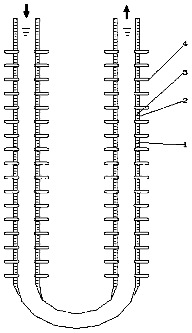
[0021] Such as Figure 1 ~ Figure 3 As shown, the outer wall of the vertical pipe in the double U-shaped pipe is covered with an oil storage pipe 2, and the upper and lower ends of the oil storage pipe are respectively sealed with the outer wall of the vertical pipe, and the gap between the oil storage pipe and the outer wall of the vertical pipe is formed. Oil storage chamber 3, the oil storage chamber is filled with heat transfer oil, the heat transfer coefficient of the heat transfer oil is 150-200w / ㎡, the heat pipe group includes several heat pipes, and several heat pipes are arranged at even intervals along the circumference of the vertical pipe. The end is inserted into the vertical pipe, and the rest is located in the soil. Several heat pipes are arranged horizontally at 90° to the vertical pipe axis of the double U-shaped pipe. In summer and winter, the heat of the medium in the double U-shaped pipe can be transferred respectively. Soil, or the heat in the soil is tran...

Embodiment 2

[0024] Such as Figure 4 As shown, the heat pipe group is an annular heat pipe, the outer wall of the vertical pipe in the outer wall of the annular heat pipe and the double U-shaped pipe, and the inner ring end of the annular heat pipe is inserted into the inside of the vertical pipe to increase the working length of the heat pipe and further increase the heat exchange efficiency of the heat pipe. In areas with better soil heat transfer characteristics, or areas with abundant geothermal resources, oil storage pipes are not required, which makes the structure simpler and more convenient to manufacture.

Embodiment 3

[0026] Such as Figure 5 As shown, as the optimization scheme of Embodiment 1, the adjacent two heat pipes are moved up and down by a certain angle, because the angle of the heat pipe has a great influence on the heat exchange efficiency of the heat pipe, so the downwardly inclined heat pipe can be It is used in winter conditions, while the upward-sloping heat pipe can be used in summer conditions, and the heat conduction direction of the two heat pipes is the same under any working condition. Downslope heat pipes play a secondary role.

[0027] Both the oil storage pipe and the double U-shaped pipe in the present invention are made of polyethylene material, and the heat pipe group is made of carbon steel.


PUM


Abstract

The invention provides a dual-U-shaped tubular heat exchanger for a soil source heat pump system. The dual-U-shaped tubular heat exchanger comprises a dual-U-shaped tube, multiple layers of heat tubeassemblies are axially and evenly arranged on the outer all of each vertical tube of the dual-U-shaped tube at intervals, the inner side ends of the heat tube assemblies penetrate through the outer walls of the vertical tubes to be inserted into the vertical tubes, and sealing treatment is conducted on the joints of the inner side ends of the heat tube assemblies and the outer walls, wherein annular heat tubes or multiple heat tubes can be adopted as the heat tube assemblies. According to the dual-U-shaped tubular heat exchanger for the soil source heat pump system, heat exchange between a medium in the U-shaped tube and soil is strengthened through the good heat conduction property of the heat tubes, the heat exchange efficiency is obviously improved, therefore, the drilling depth can bedecreased, then investment is reduced, and most of the heat exchange process is completed in the shallow stratum.

Description

technical field [0001] The invention belongs to the technical field of soil source heat pumps, and in particular relates to a double U-shaped tube heat exchanger used in a soil source heat pump system. Background technique [0002] The existing U-shaped tube soil heat exchanger for soil source heat pumps has a soil thermal conductivity of 3.1w / ㎡~7.8w / ㎡. During the design process, for safety reasons, the value is generally 3.1w / ㎡. In order to meet the cooling water and soil Due to the heat transfer requirements between the two holes, a deep hole is required. For a vertical U-shaped tube heat exchanger, a hole with a depth of 80-110m is generally required. The price of a single hole is about 10,000 yuan, which is a relatively high initial investment. It is unfavorable to the development and promotion of soil source heat pumps. Secondly, the heat transfer efficiency of soil source heat pumps often fails to meet the design requirements during use. In summer and winter conditions...

Claims


Application Information

Patent Timeline
Patent Type & Authority Patents(China)
IPC IPC(8): F28D15/02F25B30/06
Inventor 李文强
Owner 中南建筑设计院股份有限公司
Learn More