Power combiner having a symmetrically arranged cooling body and power combiner arrangement

A technology of power combiner and cooling body, which is applied in connection devices, waveguide-type devices, electrical components, etc., can solve the problems of power combiner method and method change, large parasitic capacitance, etc.

Active Publication Date: 2018-02-23
HUETTINGER ELECTRONICS GMBH & CO KG
View PDF4 Cites 0 Cited by
  • Summary
  • Abstract
  • Description
  • Claims
  • Application Information

AI Technical Summary

Problems solved by technology

[0006] However, since the electrical conductor is close to the cooling body, a parasitic capacitance is generated between the cooling body and the electrical conductor: the closer the electrical conductor

Method used


Image

  • Power combiner having a symmetrically arranged cooling body and power combiner arrangement
  • Power combiner having a symmetrically arranged cooling body and power combiner arrangement
  • Power combiner having a symmetrically arranged cooling body and power combiner arrangement

Examples


Embodiment Construction

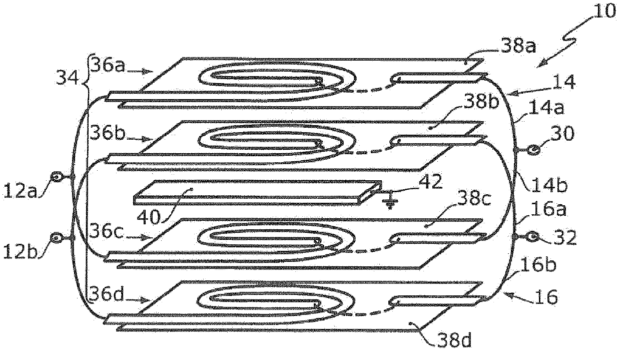
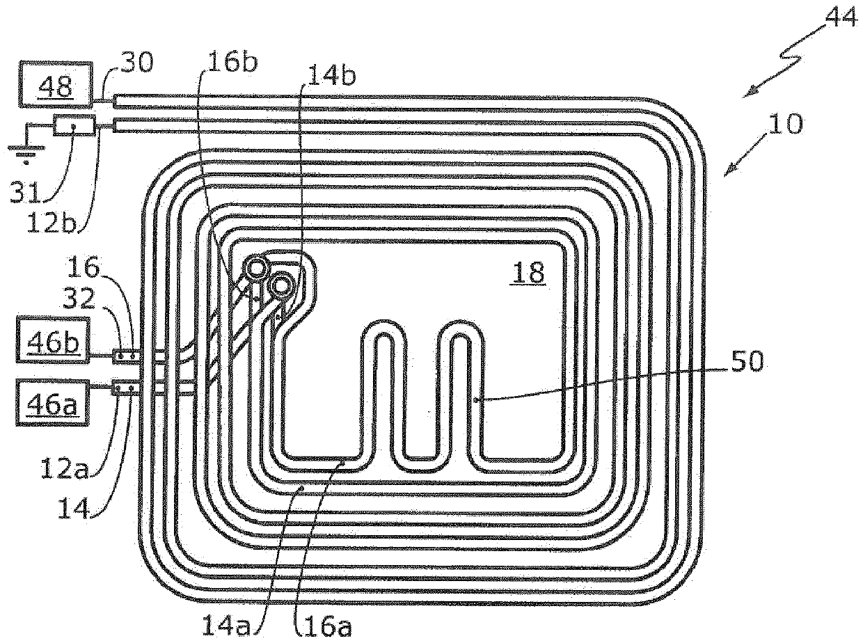
[0065] figure 1 A power combiner 10 is shown. The power combiner 10 has a first input 12 a for a first high-frequency signal and a second input 32 for a second high-frequency signal. The first input 12 a is connected to a first electrical conductor 14 . The second input 32 is connected to the second electrical conductor 16 . The electrical conductors 14, 16 are inductively and capacitively coupled to each other. A dielectric, in particular an electrically insulating substrate 18 , is arranged between the electrical conductors 14 , 16 .

[0066] More precisely, the power combiner 10 is formed in the present case by a circuit board with a dielectric, in particular an insulating substrate 18 , wherein a first capable Conductive layer 20 , on the second planar main side of the dielectric, in particular electrically insulating substrate 18 , is arranged a second electrically conductive layer 22 which extends parallel to the first electrically conductive layer.

[0067] The fir...


PUM


Abstract

The invention relates to a power combiner (10) comprising a cooling body (40). The power combiner (10) hast at least one first electrical conductor (14) and one second electrical conductor (16). The first electrical conductor (14) and the second electrical conductor (16) are generally mostly arranged equidistant from the cooling body (40). In addition, the first electrical conductor (14) and the second electrical conductor (16) can be arranged alternatingly near or at a distance from the cooling body (40). Alternatively or in addition, the cooling body (40) can be arranged between the first electrical conductor (14) and the second electrical conductor (16). Alternatively or in addition, the first electrical conductor (14) and the second electrical conductor (16) can be divided mostly intoparallel conductor parts (14a, 14b, 16a, 16b), wherein the conductor parts (14a, 14b, 16a, 16b) are distanced from the cooling body (40) in such a way that the first electrical conductor (14) and thesecond electrical conductor (16) are generally mostly at equal distance from the cooling body (40).

Description

technical field [0001] The invention relates to a power combiner for coupling and / or distributing (splitting) high-frequency signals with a frequency greater than 1 MHz into an output power greater than 100 W. Furthermore, the invention relates to a power combiner device having such a power combiner. Background technique [0002] It is known to use power combiners with electrical conductors to combine multiple high-frequency signal sources and / or to distribute (splitting) one high-frequency signal. [0003] From EP 1 699 107 A1 a power combiner is known which has a second electrical conductor spaced apart from a first electrical conductor. The first electrical conductor is capacitively and inductively coupled with the second electrical conductor. According to EP 1 699 107 A1, in order to increase the inductive coupling between the two conductors, both the first electrical conductor and the second electrical conductor can have a plurality of windings. [0004] Other power ...

Claims


Application Information

Patent Timeline
IPC IPC(8): H01P5/18
CPCH01P5/187H01P5/227H01P1/18H01P5/16
Inventor A·格雷德A·阿尔特D·格吕纳A·拉班茨
Owner HUETTINGER ELECTRONICS GMBH & CO KG
Why Eureka
Try Eureka