
Case cooling system

A technology of cooling system and chassis, applied in the direction of instruments, electrical digital data processing, digital data processing components, etc., can solve the problems of unstable computer operation, poor heat dissipation effect, and computer performance decline.

Inactive Publication Date: 2018-02-23
辜红珍
View PDF0 Cites 0 Cited by
  • Summary
  • Abstract
  • Description
  • Claims
  • Application Information

AI Technical Summary

Problems solved by technology

Most of the current computer cases use fan heat dissipation, poor heat dissipation will lead to unstable operation of the computer, and the performance of the computer will decline after a long time of operation

Method used


Image

  • Case cooling system
  • Case cooling system
  • Case cooling system

Examples


Embodiment

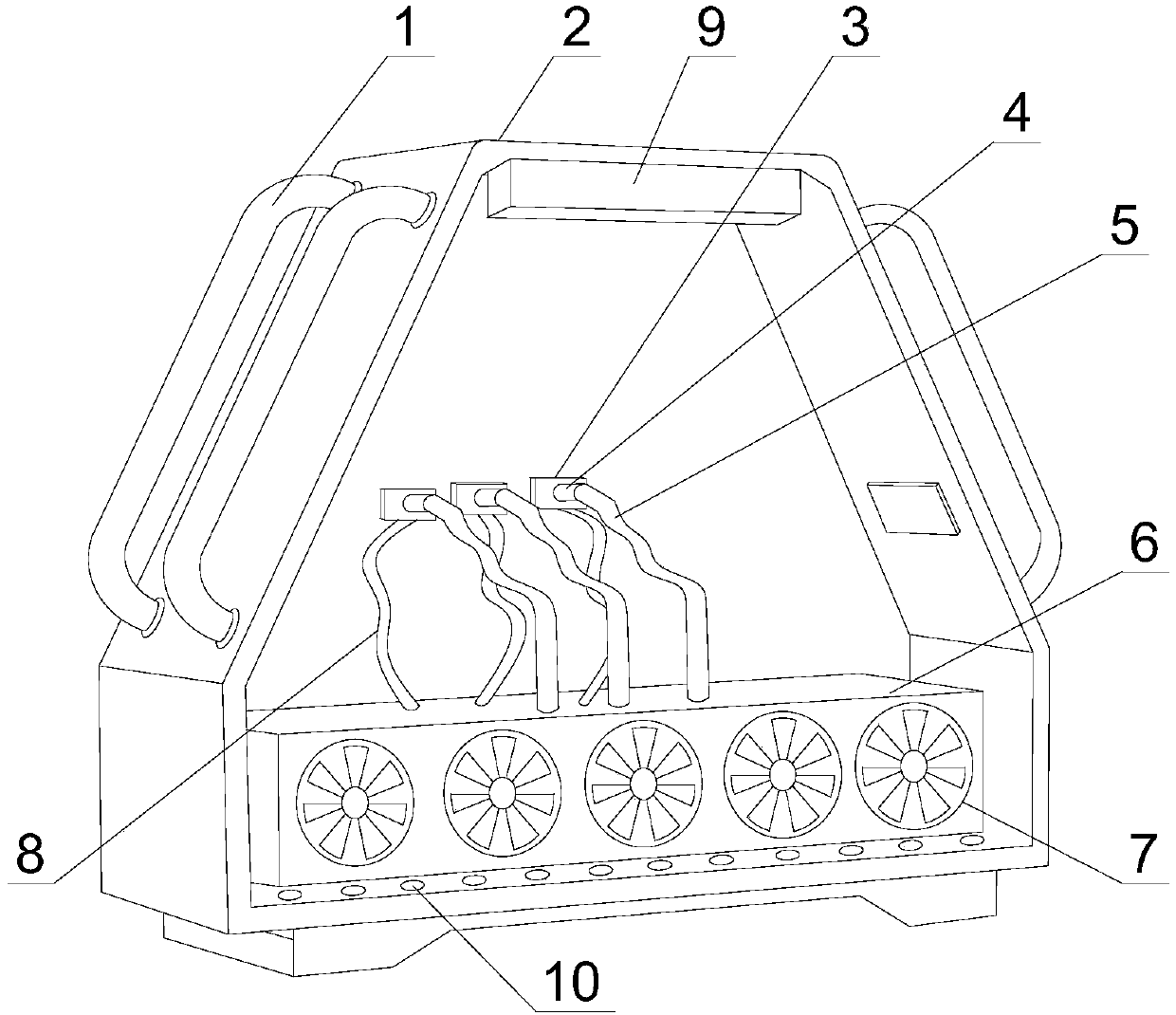
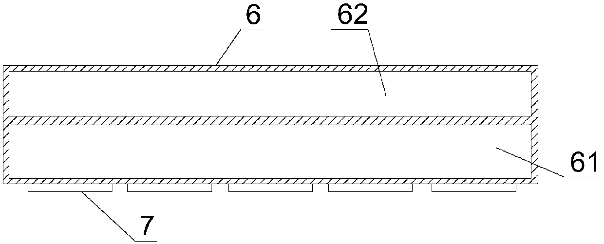
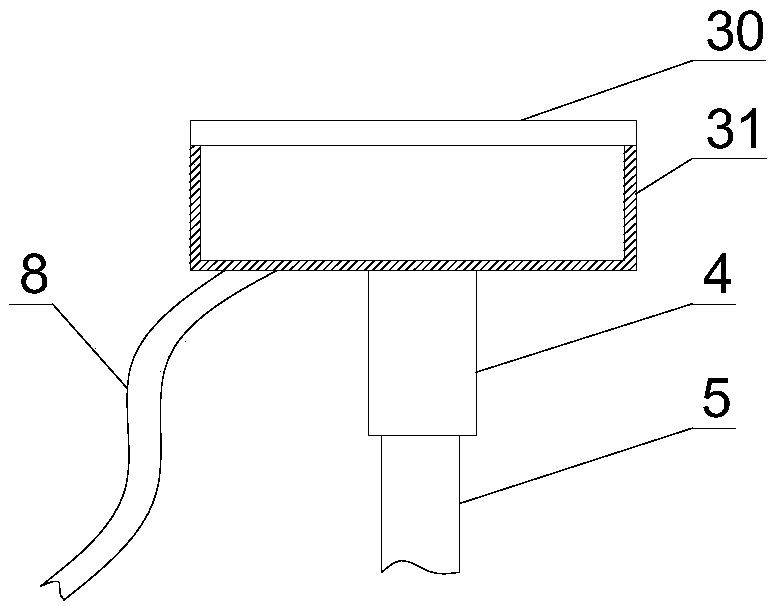
[0019] Such as Figure 1~3 As shown, a cooling system for a case includes a case 2, a cooling fan 9 is provided on the top of the case 2, a drainage hole 10 is provided at the bottom of the case 2, a water tank 6 is provided in the case 2, and the inside of the water tank 6 is divided into hot water Chamber 61 and cold water chamber 62, the outer wall of hot water chamber 61 is provided with a plurality of fans 7; Also comprises water circulation system, and water circulation system is made up of cold water pipe 5, hot water pipe 8, water pump 4 and refrigeration unit 3, the cold water pipe 5 One end is connected to the cold water chamber 62, and the other end of the cold water pipe 5 is connected to the input end of the water pump 4. The refrigeration device 3 is composed of a water box 31 and a metal plate 30, and the metal plate 30 is fixed on one side of the water box 31. Screw holes are provided on the plate 30, and the output end of the water pump 4 is connected to the w...


PUM


Abstract

The invention discloses a heat dissipation system for a case, which mainly relates to computer equipment. The direction is facing downward, which can cool down the inside of the chassis. Because the temperature of the air blown by the air cooler is low, the temperature difference between the inside and outside of the chassis is large, and condensation may occur in the chassis. Water drains.

Description

technical field [0001] The invention relates to the field of computer equipment, in particular to a case cooling system. Background technique [0002] As a part of computer accessories, the computer case is mainly used to place and fix various computer accessories, and to play the role of support and protection. Most of the current computer cases use fan heat dissipation, poor heat dissipation will lead to unstable operation of the computer, and the performance of the computer will decline after a long time of operation. Contents of the invention [0003] The purpose of the present invention is to solve the problem that most of the current computer cases adopt fan type heat dissipation, the heat dissipation effect of which is poor, and the performance of the computer will decline after running for a long time. In view of the above problems, the present invention provides a chassis cooling system, the application of which can enhance the cooling effect of the chassis. [...

Claims


Application Information

Patent Timeline
IPC IPC(8): G06F1/20
CPCG06F1/20G06F2200/201
Inventor 辜红珍
Owner 辜红珍
Learn More