
A micro-combustor based on gas preheating and enhanced reflux to improve flame stability

A micro-burner, gas preheating technology, applied in the direction of gas fuel burner, burner, combustion type, etc., can solve the problems of being easily affected by external conditions, short residence time, poor flame stability, etc., to shorten the ignition delay time, reducing the energy required for ignition, reducing the effect of exhaust heat loss

Active Publication Date: 2019-04-12
HUAZHONG UNIV OF SCI & TECH
View PDF5 Cites 2 Cited by
  • Summary
  • Abstract
  • Description
  • Claims
  • Application Information

AI Technical Summary

Problems solved by technology

(1) Due to the poor rigidity of the flame in the micro burner, it is easily affected by external conditions, which easily leads to poor flame stability
(2) Due to the high specific surface area of ​​the micro-burner, the heat is seriously lost, and it is prone to heat fire and free radical fire
(3) The residence time of chemical reaction components is short, which is basically the same order of magnitude as the chemical reaction time of hydrocarbon / air, which easily leads to low combustion efficiency

Method used


Image

  • A micro-combustor based on gas preheating and enhanced reflux to improve flame stability
  • A micro-combustor based on gas preheating and enhanced reflux to improve flame stability
  • A micro-combustor based on gas preheating and enhanced reflux to improve flame stability

Examples


Embodiment Construction

[0020] In order to make the object, technical solution and advantages of the present invention clearer, the present invention will be further described in detail below in conjunction with the accompanying drawings and preferred embodiments. It should be understood that the preferred embodiments described here are only used to explain the present invention, not to limit the present invention.

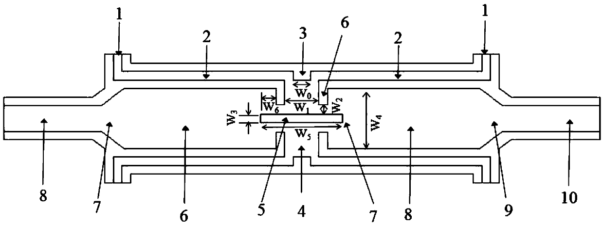
[0021] Such as figure 1 As shown, the micro burner provided by the preferred embodiment of the present invention includes a gas inlet 1, a gas preheating channel 2, a first combustion stabilization boss 3, a low-speed small cavity combustion chamber 4, a partition 5, a second combustion stabilization boss Platform 6, third stable combustion boss 7, high-speed large-cavity combustion chamber 8, high-speed large-cavity combustion chamber tapering outlet 9 and tail gas outlet 10. .

[0022] The gas preheating channel 2, the low-speed small-cavity combustion chamber 4 and the high-speed la...


PUM


Abstract

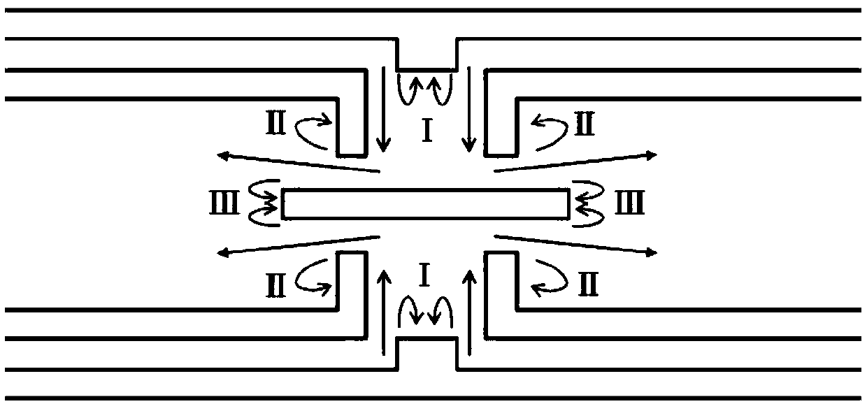
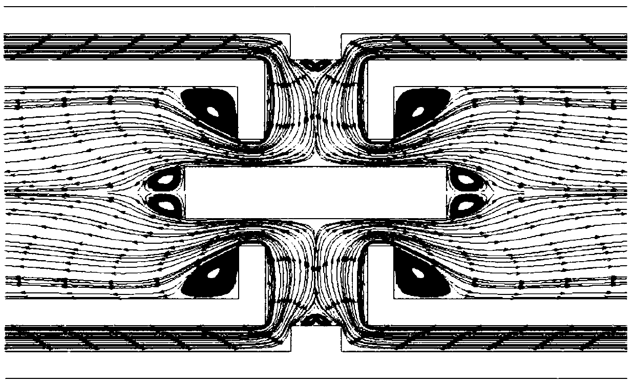
The invention discloses a micro-combustor with flame stability enhanced by gas preheating and reflux reinforcing. The micro-combustor comprises two low-speed small-cavity combustion chambers which arearranged up and down, two high-speed large-cavity combustion chambers are arranged on the left side and the right side of the low-speed small-cavity combustion chambers, and the two low-speed small-cavity combustion chambers communicates with the two high-speed large-cavity combustion chambers; the upper wall face and the lower wall face communicating with the two high-speed large-cavity combustion chambers are each provided with a gas preheating channel, and the gas preheating channels correspondingly communicate with the upper and lower low-speed small cavity combustion chambers; and firstreflux areas are formed in the communication positions of gas preheating channels and the low-speed small-cavity combustion chambers, second reflux areas are formed in the communication positions of the low-speed small-cavity combustion chambers and the high-speed large-cavity combustion chambers, and third reflux areas are formed in the positions, closes to gas inlets, of the insides of the high-speed large-cavity combustion chambers. According to the micro-combustor, combusting preheating is carried out so that the energy needed by ignition can be reduced, and the ignition delay time can beshortened; and the low-speed combustion chambers and the high-speed combustion chambers are arranged at the same time so that the ignition flameout limit can be increased, and the inlet speed can be widened.

Description

technical field [0001] The invention belongs to the technical field of micro-scale power generation, and more specifically relates to a micro-combustor that improves flame stability based on gas preheating and enhanced reflux. Background technique [0002] With the rapid development of micro-processing technology and its unique advantages, such as small size, light weight, high energy density, and continuous operation, micro-combustors are widely used in various micro-electromechanical systems and equipment. At the same time, oxygen and hydrocarbon fuels have ten times the energy density of conventional batteries. Therefore, combustion-based tiny power devices have great potential to replace conventional batteries. This type of power device can convert the chemical energy of hydrocarbon fuel into heat energy through combustion, and rely on various energy conversion methods to provide power or electricity for micro-electromechanical systems. But this kind of equipment also ...

Claims


Application Information

Patent Timeline
Patent Type & Authority Patents(China)
IPC IPC(8): F23D14/26F23D14/66
CPCF23D14/26F23D14/66Y02E20/34
Inventor 马仑方庆艳谭鹏李鑫张小培张成陈刚
Owner HUAZHONG UNIV OF SCI & TECH
Learn More