
Magnetic sliding shoe pair for axial plunger pump and motor and control method

An axial piston pump and control method technology, which is applied in the direction of pumps, pump components, multi-cylinder pumps, etc., can solve the problem of not improving the wear of the bearing surface of the sliding shoe, increasing the difficulty of maintaining a stable oil film thickness, and being unable to adapt to the sliding shoe. It can solve the problems of force and other problems, so as to achieve the effect of sensitive transformation, improvement of electromagnetic force component, and reduction of electromagnetic force fluctuation.

Active Publication Date: 2018-02-23
ANHUI UNIV OF SCI & TECH
View PDF6 Cites 16 Cited by
  • Summary
  • Abstract
  • Description
  • Claims
  • Application Information

AI Technical Summary

Problems solved by technology

[0006] First, the electromagnetic force uses the suction force to adsorb the sliding shoe pair on the swash plate. When the thickness of the oil film decreases, the electromagnetic force increases, and the thickness of the oil film can only be maintained by the stiffness of the oil film itself, which increases the difficulty of maintaining a stable oil film thickness.
[0007] Second, the distribution of the electromagnetic force is not ideal, and the electromagnetic force fluctuates greatly along the circular motion direction of the slider pair, which is not conducive to the stable operation of the slider pair
[0008] Third, the single application of electromagnetic force can only absorb the sliding shoe, and cannot adapt to the stress on the sliding shoe during the complex working process of the axial piston pump / motor, nor does it improve the wear of the bearing surface of the sliding shoe

Method used


Image

  • Magnetic sliding shoe pair for axial plunger pump and motor and control method
  • Magnetic sliding shoe pair for axial plunger pump and motor and control method
  • Magnetic sliding shoe pair for axial plunger pump and motor and control method

Examples


Embodiment Construction

[0034] The following will clearly and completely describe the technical solutions in the embodiments of the present invention with reference to the accompanying drawings in the embodiments of the present invention. Obviously, the described embodiments are only some, not all, embodiments of the present invention. Based on the embodiments of the present invention, all other embodiments obtained by persons of ordinary skill in the art without making creative efforts belong to the protection scope of the present invention.

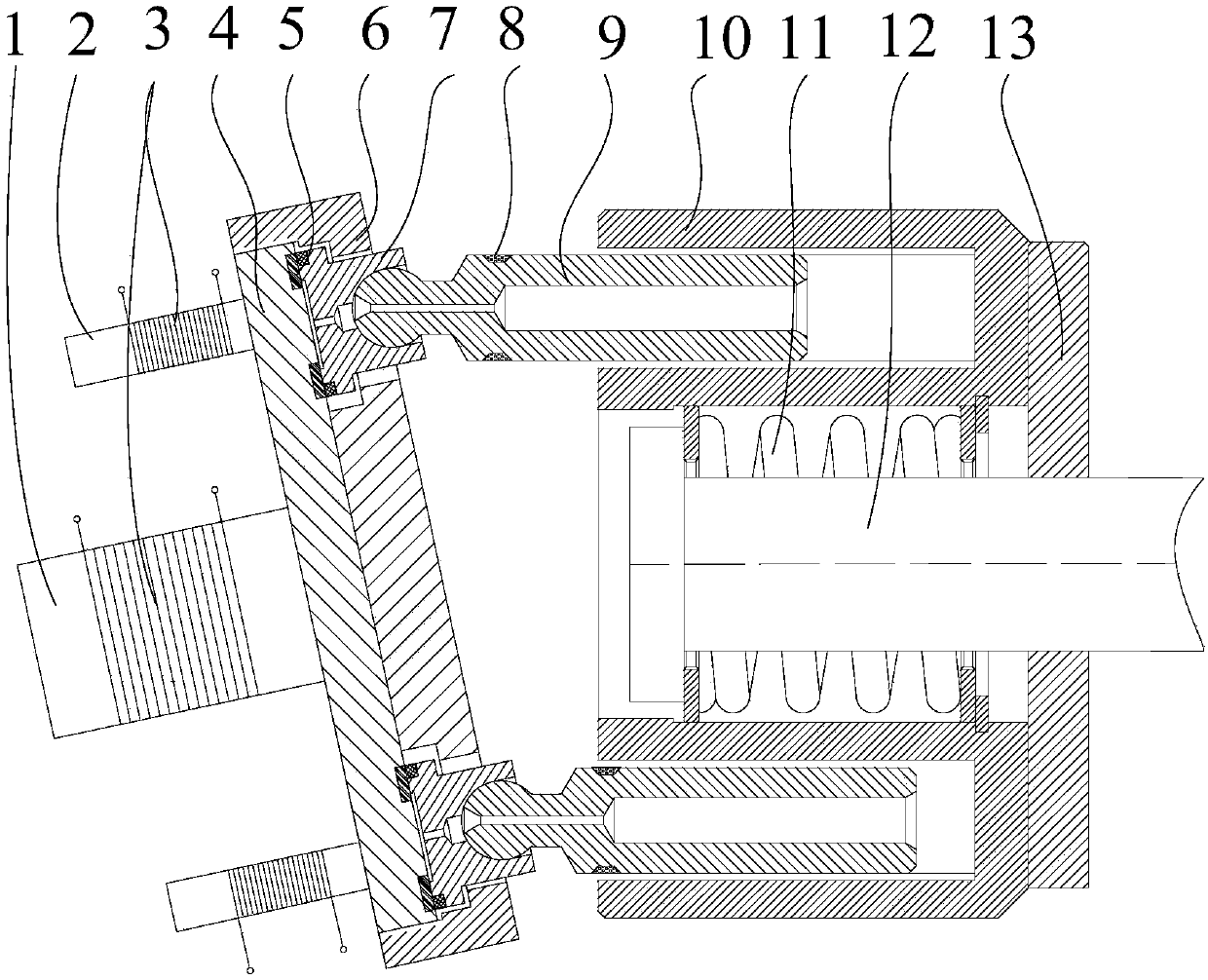
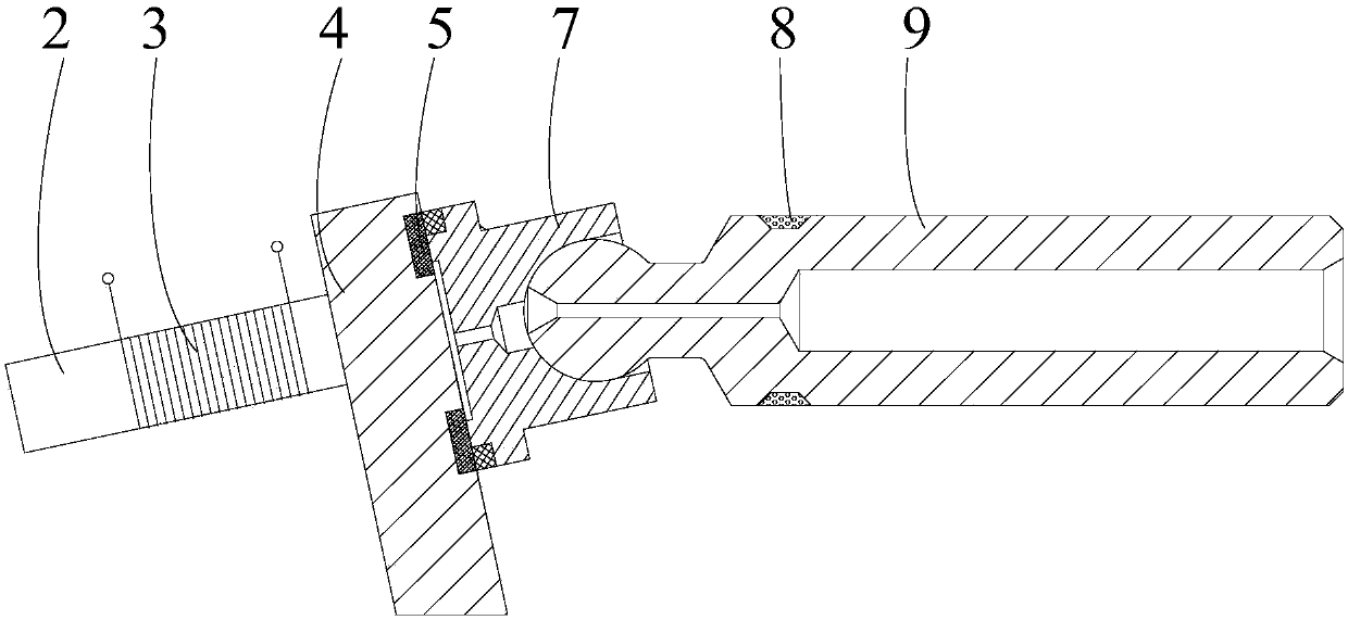
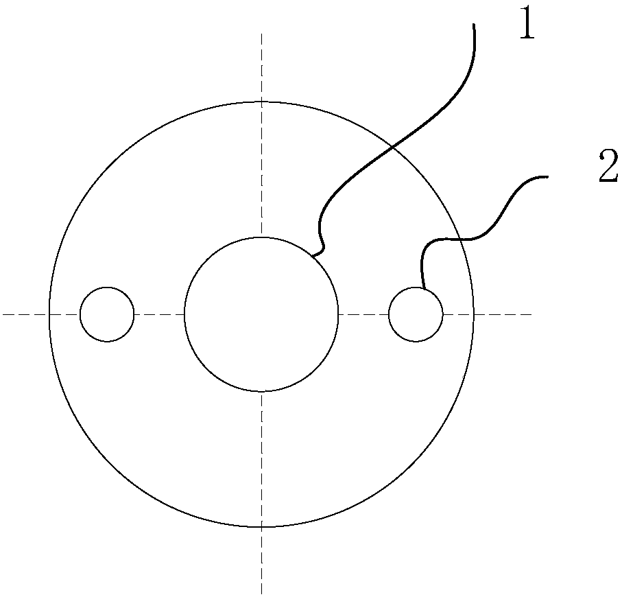
[0035] see figure 1 , figure 2 , image 3 , Figure 4 with Figure 5 Shown: A magnetic sliding shoe pair for an axial piston pump and motor and its control method, including a main iron core 1, an auxiliary iron core 2, a coil 3, a swash plate 4, a micro-shaped hole 5, an annular pressure plate 6, and a sliding shoe 7. Coil kit 8, plunger 9, cylinder body 10, spring 11, drive shaft 12, and distribution plate 13, characterized in that: the central position...


PUM


Abstract

The invention discloses a magnetic sliding shoe pair for an axial plunger pump and a motor and a control method. The magnetic sliding shoe pair comprises plungers, coil sleeve pieces, sliding shoes and an inclined disc; closing coils are arranged in the coil sleeve pieces; micro modeling holes are formed in the bearing face, making contact with the sliding shoes, of the end face of the inclined disc and are in a semi-spherical shape; and the back face of the inclined disc is provided with a main iron core and two auxiliary iron cores, the iron cores are all wound with coils, and the coils areconnected with an external alternating current power supply. An electromagnetic force self feedback regulation mode is provided so that the stable working state of the sliding shoe pair can be ensured. When the axial plunger pump / motor works, the coils are powered on, a magnetic field is generated, accordingly, the sliding shoes are attracted to the inclined disc, meanwhile, the coil sleeve piecesgenerate an induced magnetic field, electromagnetic force applied to the sliding shoes is converted into attraction force or repulsive force along with moving of the sliding shoes, a hydrodynamic effect is formed when the sliding shoes are under a complex stressed condition, the bearing face of the inclined disc is subjected to micro modeling design, thus, the oil film rigidity is improved, and the friction coefficient is reduced.

Description

technical field [0001] The invention relates to the technical field of axial piston pumps and motors, in particular to a magnetic sliding shoe pair for axial piston pumps and motors and a control method. Background technique [0002] Axial piston pump / motor is one of the important power components and executive components in the hydraulic system. It is widely used in industrial, agricultural, coal mine, military and other hydraulic systems. It is the two most widely used hydraulic components in modern hydraulic components. one. At the same time, due to the complex structure of the axial piston pump / motor, the requirements for the manufacturing process and materials are very high, so it is one of the hydraulic components with high technical content. [0003] In recent years, with the take-off of my country's economy, the development of materials, manufacturing, electronics and other technologies, in the process of industrial modernization and large-scale urbanization, the ax...

Claims


Application Information

Patent Timeline
IPC IPC(8): F04B1/22F04B53/18F04B53/00F04B53/14
CPCF04B1/124F04B1/126F04B1/2078F04B1/22F04B53/18
Inventor 邓海顺杨勇康王海峰王庆春毛飞宇汪春燕何士举王涛
Owner ANHUI UNIV OF SCI & TECH
Learn More